Project: Installing DROs on DRO-Pros C8 Lathe
Over the last few years, DRO PROS has become well known among home-shop machinists as a great source specializing in DROs for lathes, mills and, well, any other machine that you may want to install them on.
Anyone who’s installed DROs on their machines, or has considered doing so, has no doubt discovered that there are many brands and suppliers to choose from - from the well-known larger suppliers such as Grizzly, Travers, MSC and Enco to offshore vendors selling DROs on eBay.
What sets DRO PROS apart from the others is their specialized focus on DROs and their excellent documentation, service and support.
On the DRO PROS web site, you’ll find many documents that go into detail of some of the finer points of choosing, installing and using DROs, along with a full range of high-quality videos that show the actual operations.
Unlike some of the amateur videos you might find on YouTube, the DRO PROS videos are clear, sharp, understandable, and follow a logical sequence to explain the topic being discussed.
So, even if you’re considering buying DROs from another source, be sure to check out the DRO PROS web site - you’ll learn a lot that will help you make your purchasing and installation decisions.
Some months back, while I was working on my review of the C8 11x30 lathe from Sieg, I received notice from Sieg that DRO PROS had contracted to become the first U.S. dealer to sell the SC8.
Beginning around June, 2013, DRO PROS received their first shipment of lathes and expanded their business into this new offering.
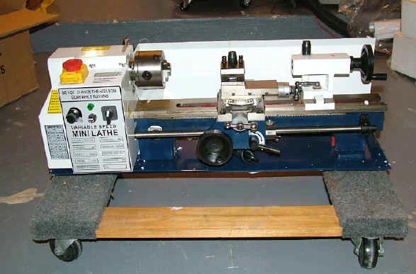
The SC8 model has the powerful, high-torque brushless DC motor, while the C8 model that I reviewed has a traditional AC induction motor and belt-pulley system to select spindle speeds.
Not only does the SC8 have more torque, it is a lot more convenient to use, since you can instantly change speeds at any time - even during a cut, to reduce chatter, for example.
Additionally, the intelligent controller electronics in the SC8 quickly adjust the torque of the motor to maintain a constant RPM setting, as displayed on the integrated digital tachometer, when the load on the motor changes due to cutting forces.
For example, as you plunge the cutting tool into the workpiece during a cutoff operation, the motor will momentarily slow down a little, due to the sudden increase in load, then quickly accelerate to resume the original speed setting.
Time goes by…
How I met Mike
A few weeks ago I received an email from a fellow hobbyist letting me know that, after reading my review, he’d made a decision to buy the SC8 from DRO PROS.
Even better, though, he was located within convenient driving distance of mini-lathe.com world headquarters! I told my new friend, Mike, that I’d love to visit his shop to see the new lathe when it arrived.
Not long after that, Mike emailed me to invite me to see the newly installed lathe. I was a little disappointed that I didn’t get to help him move it into his basement shop (always an adventure!!), but happy to get to see new lathe.
The lathe arrived in great shape. The only defect that I noticed was some slight staining of the white paint due to a little oil seeping out around the drive shaft.
I’ve seen that same type of seepage on several other lathes from various manufacturers. It’s a common occurrence, but has no effect on lathe operation.
It tends to be more visible on this lathe due to the white paint scheme. On the other hand, the white paint brightens up the work area, makes it easier to see what’s happening where blade meets metal and therefore safer.
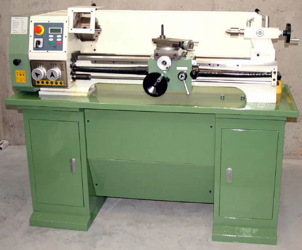
My own C8 lathe is mounted on a shop-made wooden bench, so this is the first time that I had seen the Sieg factory-made lathe bench.
I was impressed by its sturdiness, the quality of the door handles, and the convenient storage space provided by the two cabinets.
The lathe sits in a tray-like top, which acts as a collecting pan for recycling coolant, in case you decide to outfit your SC8 with a coolant flow system.
The Deal is Sealed
Before long, Mike and I got talking about the advantages of having DROs on the lathe - especially on a lathe in this class, which is capable of some really fine work.
Mike had considered ordering DROs with the lathe, but had then decided to defer that purchase until after he gained some experience with the lathe.
As all home machinists discover early in their endeavors, when working on a lathe, and even more-so, on a mill, you need a convenient way to keep track of how much material you have removed from the workpiece.
When you’re starting out, simply marking guide-lines on the workpiece and cutting until you reach them, is often good enough, but as your skills develop and you’re challenged to work to more demanding tolerances, better accuracy is needed.
Over the last few weeks I’d been exchanging email with DRO PROS about the SC8 lathe. They were kind enough to send me an electronic copy of their SC8 user manual, which was more up-to-date than the one that I had received with the C8 lathe that I reviewed.
We discussed the possibility of me reviewing their magnetic-technology low-profile DROs, but I was already in the process of installing a set of DROs that Sieg had sent with the C8.
Then it occurred to me that I could do a project article on installing a set of DRO PROS magnetic DROs on Mike’s new lathe.
After some finagling and horse-trading with DRO PROS and getting Mike’s OK to do the article, we were able to work out a deal to provide Mike with a set of DROs at a reduced price.
Kind of a win-win-win for all involved.
Magnetic DRO Advantages
Over the years, I’ve enhanced my machines by adding adjustable dial indicators, relatively inexpensive capacitive scales and, more recently, as finances have permitted, industrial-quality glass scales.
Not surprisingly, the high-end scales are more precise, more stable, easier to read and a lot more convenient to use.
Also, and especially for milling operations, the high-end DROs provide a number of time-saving computerized functions for common operations such as drilling bolt-hole circles and machining arcs.
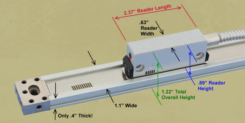
For this project, we decided to use DRO PROS top-of-the-line magnetic DROs. While a little more expensive than capacitive or glass technologies, the magnetic DROs yield an immediate return on investment due to their installation and operational benefits.
First of all, their thin low-profile design simplifies the installation and makes them safer when in use, since they can snug right up against the cross slide or bed of the lathe.
Thus mounted, they are better protected and are less likely to snag on something or hit the spinning chuck.
Secondly, they can be cut to length for optimum fit in the available space. DROs that use glass measuring scales, for rather obvious reasons, can’t be cut, and so they may extend beyond the ends of the cross-slide where they are more exposed to possible damage and can get in the way of operations.
Third, the magnetic DROs are nearly impervious to swarf, cutting fluids, lubricants, dust, impact and other hazards common the the lathe operating environment.
Naturally, they should be protected as much as possible, but are exceptionally tough.
To top off the list of benefits, in this kit, DRO PROS provides extra-high-resolution scales with 1 micron resolution, where competing scale technologies offer only 5 micron resolution.
While this may seem like such a small value that it’s negligible, it has real operating implications when the cross-slide is set to read out in diameter mode, which is one of the big benefits of using DROs.
For a full explanation of why this is so, see this document on the DRO PROS web site.
And while its not really a feature of the magnetic DROs, it’s nice to know that if you have any questions or concerns at any stage during the process from conception to installation or while in operation, experts are available by phone or email to help you out.
Due to their extensive in-house experience with their products, the staff at DRO PROS understand the technical issues and understand the language of machine shop operations.
Last, but not least, the magnetic DROs are covered by a 6-year warranty.
The DROs Arrive
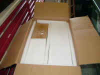
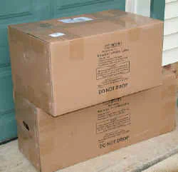
The DROs arrived via UPS in perfect condition after a trip across the U.S. that took about six days.
All the components for the installation were securely packaged in boxes within boxes with labels clearly identifying the contents of each box.
A layer of foam padding further protected the contents during shipment.
Down to Work
After unpacking the DROs, Mike and I got down to work on the installation. Mike is a very accomplished woodworker and model maker (among several other skills and interests), but only recently decided to delve into the deep mysteries of home-shop machining.
Consequently, he does not yet have a fully equipped machine shop, so I brought with me some tools, such as 1-2-3 and 4-5-6 blocks, parallels, metric drills and taps, dial-indicators, etc that I had found useful in my earlier DRO installation projects.
Armed with the excellent written documentation, and having watched the DRO PROS online videos in advance, Mike and I soon established an efficient working rhythm.
Mike handled those parts of the project that were well-suited to his skills, while I focused on some of the more arcane tasks, such as tapping the small metric threads in the ends of the DRO scales after cutting the scales for optimum fit on the lathe - something that you just can’t do with other varieties of scales.
Choosing X-axis Scale Location
Regardless of which type of measuring device you install on your machine, figuring out the “best” location and mounting method is a significant part of the effort.
Ideally, you want the scales to be as compact as possible, mounted in close proximity to machine castings, so that they don’t have ends sticking out that could be damaged by a spinning chuck, a dropped tool, or caught on a loose sleeve cuff.
(Which is why, of course, we always wear short-sleeve shirts or tight-fitting cuffs when working with machine tools, right?)
In practice, though, placement is nearly always a compromise: most scales are available only in fixed length increments and must be fitted into a space that may have curves, projections and adjustment or oiling points that can’t be covered over.
The DRO PROS magnetic DROs have a very thin profile and can be cut to length, for the best possible fit within the available space.
So our first order of business was to decide where we’d place the X-axis (cross-slide) and Z-axis (carriage) DROs.
I like to start with the X-axis because it usually is the more challenging of the two, and for most shops, being able to measure the diameter or radius of the workpiece has more immediate benefit than measuring the length of a cut.
In one of their videos, DRO PROS recommends, for good reason, installing the X-axis scale on the right side of the cross-slide.
Installing it on the left side of the cross-slide would make the scale more exposed to the rotating chuck and workpiece, a dropped chuck or chuck wrench, cutting fluids and other potential hazards that are less likely to occur on the right side.
However, on the SC8 lathe, the gib-adjusting screws, carriage lock and cross-slide lock are all located on the right side of the cross-slide.
Therefore, it is pretty much a no-brainer that the scale needs to go on the left side, with all due respect for the possible hazards of that location.
Also, on both sides of the cross-slide, there are oil ports which, ideally, should not be covered up by the installation.
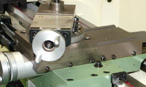
Right side of cross-slide
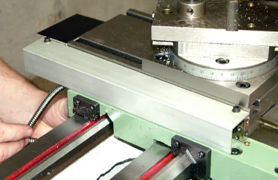
The left side of the cross slide is free from any such interference and therefore is the logical choice of location for the X-axis DRO scale on the SC8 lathe.
And fortunately, due to the very narrow profile of the DRO PROS magnetic DROs, the scale does not protrude into the area of the chuck, and is well-protected by being flush against the side of the cross-slide while the read-head is protected by the saddle.
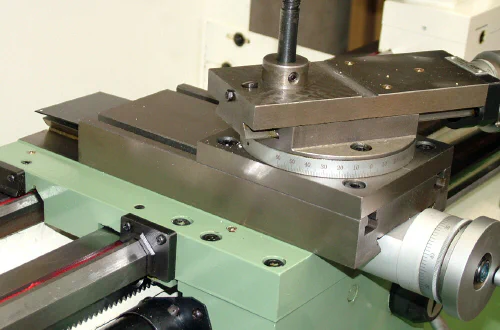
Left side of cross-slide
Mounting the X-axis Scale
With that decision made, the next concern was the exact positioning of the scale along the side of the cross slide, the location of the read-head, and the optimum length to which to cut the scale.
DRO PROS provides excellent documentation as well as a worksheet to help you determine the length to which to cut the scale.
While not really necessary, cutting the scale to size is quite easy to do and minimizes any overhang of the scale beyond the sides of the cross slide, making the installation as rugged as possible.
Using the provided worksheets, Mike worked out the length to which to cut the scale. After cutting, the scale could be mounted with the front end flush with the front edge of the cross slide, and the back edge extending about an inch beyond the back edge of the cross slide.
DRO PROS recommends using a Diablo non-ferrous blade in a chop-saw as the preferred tool for cutting the scale to length, but makes it clear that other methods, including the humble hand-held hacksaw (i.e. the Armstrong saw) can also be used.
After removing the thin stainless steel strip from the scale, as described in the DRO PROS instructions, Mike cut the scale to length on his newly-acquired Jet 4x6 bandsaw.
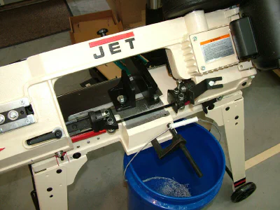
Mike’s new bandsaw
A little touch-up of the cut end on the disk sander, and we had a smooth and square end.
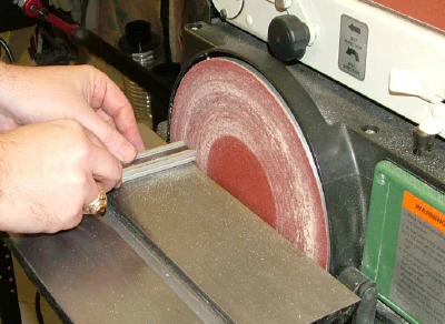
Smoothing the cut end on a disk sander
Note: some time later, Mike and I noticed that the bandsaw was cutting very poorly. I assumed that the blade shipped with the saw might be sub-standard quality.
We swapped in a new blade and it cut very well. Later on, I was wondering if the center part of the scale might be made from very hard metal which dulled the bandsaw blade.
I haven’t had a chance to test this theory yet, but be aware that cutting these scales with a hacksaw or bandsaw may sacrifice a blade.
I then tackled the somewhat delicate job of tapping the holes in the cut end of the scale so that the end cap can be reinstalled. The job is delicate because of the small diameter M3x.
5 tap required. Those of you who have “been there and done that”, know that aluminum often has a tendency to “grab” the tap, possibly causing the tip of the tap to break off in the hole - especially when using a small diameter and somewhat delicate tap.
Not only does that ruin a valuable tap, but the tip of the broken tap can be nearly impossible to remove, thus creating a major headache in how to work around that problem.
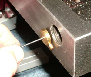
Tapping the ends of the cut-off scale
Note: when turning the tap, the tap guide is held firmly against the workpiece.
I clamped the scale to the side of a 4-5-6 block to hold it vertically. A few drops of Tap Magic Aluminum cutting fluid helped to keep the aluminum from seizing the tap, and a small shop-made tap guide helped to keep the tap square with the end of the scale.
Heart pounding, hands trembling and sweat dripping from my brow, I succeeded in tapping the holes without breaking the tap. Phew! For more tips on tapping check out my Premium Content page.
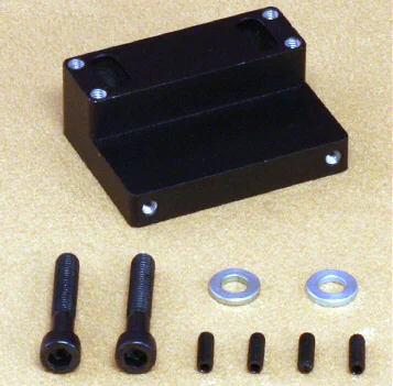
The DRO kit comes with a set of bolts, washers and cast aluminum brackets that can be cut, thinned, drilled, tapped or otherwise adapted to just about any mounting situation.
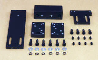
DRO mounting components
Of course, you’re also free to come up with your own innovations for mounting the scales and sensors, and sometimes making your own bracket or spacer can be quicker or offer a more convenient or custom-fitted solution.
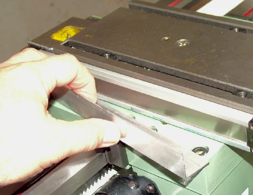
To support the back end of the slide, and to provide a place for the mounting screws to secure the scale, Mike and I fabricated an L-bracket from some scrap aluminum sheet, 0.70" (1.75mm) thick, that I had brought along for just such a contingency.
Laying out hole positions on shop-made bracket
Mike suggested that we install the bracket by using the already existing screws that support the small chip shield that extends from the back of the cross slide.
That was a great idea, since drilling and tapping holes in cast iron can be tricky. The drilling itself is easy enough, but when using a hand-held drill as is necessary in situations like this, the drill bit may drift away from the place where the hole is intended to go, or the hole may become oversize.
Lacking any sort of sophisticated sheet-metal tools, Mike rough-cut the bracket on his 4x6 bandsaw. After a little fine-tuning on Mike’s small Grizzly belt sander, the bracket was taking shape.
I made the right-angle bend using a vise and then shaping it to a sharper bend by beating it (not quite to death) with a dead-blow hammer against a 4-5-6 block.
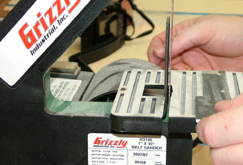
Trimming the bracket on the belt sander
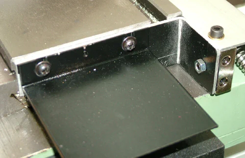
Shop-made L-bracket
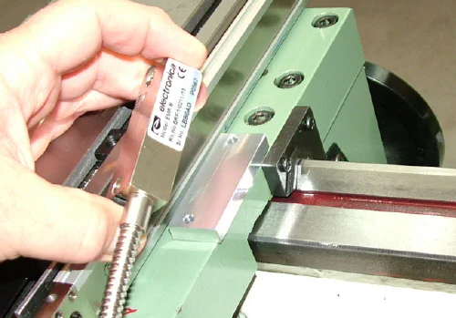
Now it was time to determine the final position of the scale on the cross slide and drill the mounting hole.
We used a section of aluminum L-bracket as a spacer to ensure that the bottom edge of the scale was level with the saddle but that there was a gap of about 1/16" between the lower edge of the scale and the top of the saddle.
The gap is necessary because the scale moves back and forth with the cross slide. With the spacer in place, we used a transfer punch to mark the position at which to drill the mounting hole for the right (front) end of the scale.
L-bracket spacer under scale
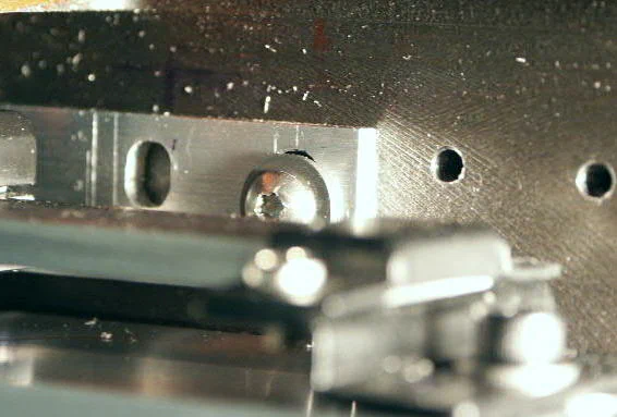
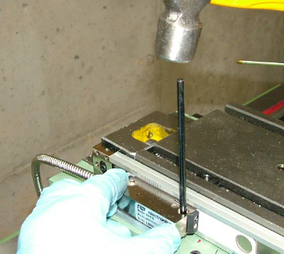
After marking out the position of the DRO on the cross-slide, the next step was to drill the mounting hole. Since the back end of the DRO is supported by the bracket, only one hole needed to be drilled in the cross slide.
We marked the hole position with a center punch, then started the hole with a center drill at low speed.
I like to use the center drill first because its stiff and does not flex when starting the hole. It leaves a cone-shaped depression that helps the regular drill bit stay on target.
Next we used a drill about 25% smaller in diameter than the tap drill. This helps to ensure that the final hole diameter is not oversized, which could lead to weak threads.
When drilling in cast iron using a hand-held drill, it’s easy to drill the hole oversize due to unintended movement of the drill while attempting to hold it steady.
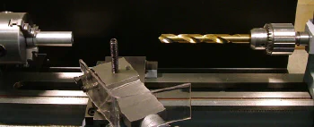
Center drilling the mounting hole in the cross-slide
Mounting the X-axis Sensor Head
The sensor must be positioned so that it does not run off the end of the scale at either end of the cross slide movement.
For most installations, it ends up being centered when the cross slide is about at the middle of its range of movement, but, to accommodate unusual situations on some machines, the scale and sensor sometimes are offset from a centered location.
That was not necessary on this lathe.
To line up the sensor with the scale, we needed a spacer block, about 1/4" thick, underneath the sensor head. The DRO PROS kit does provide a mounting bracket, which we could have modified, but since we only needed a spacer, we chose not to use it:
Mounting bracket included with DRO kit
And, although we could have made it from hardwood, in my role of subtly transforming Mike into a metal-worker, I suggested that we make the block from aluminum plate stock.
Not having the facilities in Mike’s shop to easily make such a block, I made it at my shop that night using the mini mill.
Note: for those of you who don’t (yet) have a mini mill or similar tool, all of the necessary operations can be accomplished by other means.
Then again, as I kept telling Mike, if you’re gonna have a nice lathe like this, you really should have a mini mill (or maybe a bigger mill)! ;-)
The next step was to mark the position of the screw holes for the sensor unit. The sensor is screwed to the saddle and remains in a fixed position while the scale slides back and forth past it as the cross slide is moved.
A thin plastic spacer is provided by the DRO manufacturer to ensure that the face of the sensor is the correct distance away from the scale when laying out the location for the sensor.
We used a transfer punch to mark the locations for the mounting screws on the lathe saddle.
Marking the hole locations. Note spacer under sensor head.
The next job was to cut the cover to size and mount it on the DRO scale. I made the cut in my shop using the mini mill - this time with a thin saw blade to cut off a strip from what would be the bottom edge of the cover.
Cutting the X-axis scale cover
To keep the workpiece from chattering, I stopped the saw and repositioned the workpiece to the left each time the saw approached the unsupported right edge.
Cover in place over the X-axis scale and sensor
We used 4mm socket-head cap screws temporarily to secure the cover as they were all that we had on hand. Button head cap screws are recommended for a more finished appearance.
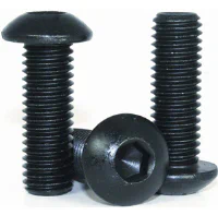
Button head cap screws
That being done, I decided that we really needed to have a mini mill on-site for the remainder of the project, so at home that night, I rigged up the mini mill so that I could operate it out of the back of my Tacoma pickup.
With the help of my handy hydraulic table and ceiling-mounted winch, loading the mini mill into the truck was pretty easy.
A few ratcheted tie-down straps secured the load for travel, and I was ready to hit the road. Some readers may question whether this effort really was necessary. Well, all I can say is that they just don’t understand…
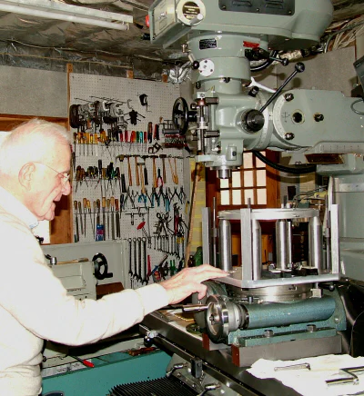
Mini mill set up for mobile stealth night ops
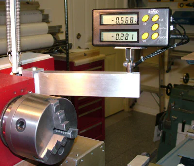
Mounting the Control Panel
So that we could could do a quick test to make sure that the X-axis readout was working properly, we decided to mount the control panel next.
When installing the DROs on my C6 lathe in 2012, I found that aluminum channel is a useful support material.
It was strong enough that I could cantilever the display unit out on a moveable arm, thus providing a lot of flexibility and convenience in positioning it for whatever job I happened to be working on.
Display unit installed on C6 lathe
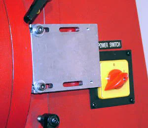
Not having any similar material readily available, Mike employed his woodworking skills and tools and quickly had a temporary mount in place. Naturally, when time permits, the wood must be replaced by metal.
Of course the display console has a slew of features, but I didn’t get an opportunity to see it in action yet. My job was to help Mike get the DROs installed.
In my own use of the DROs on my lathe, I use them primarily for measuring the current diameter of the workpiece and for marking off distances along the length of the workpiece for various features.
Aside from the ability to read either in inch or metric units, and to switch instantly between them, another cool feature of the DRO is the ability to directly read the diameter of the workpiece rather than the radius.
You’re probably aware that on most imported lathes, when advancing the cross-slide, the units on the handwheel dial read out the distance that the cross-slide has been advanced.
The diameter of the workpiece actually is reduced by twice that amount - which can quickly lead to trouble if you’re not aware of it.
If that’s not enough to trip you up, on many imported lathes the calibrations are marked in inches but the leadscrew actually is metric.
Thus, when the dial says you have advanced by 0.001", you really have advanced only by 0.00098", a small discrepancy, but significant when you’re trying to work to tolerances of 0.001" or better.
While its easy to compensate for these factors, once you’re aware of them, when using a DRO, you don’t have to concern yourself with them: what you see is what you get, so the chances of making a measurement error, and possibly ruining a workpiece, are greatly reduced.
Mounting the Z-axis Scale
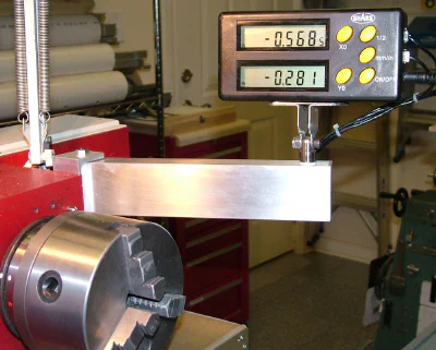
Using a dial indicator mounted on the carriage, we determined that the back of the bed casting was accurately parallel with the ways.
There is a raised area on the casting where an optional mini mill head can be bolted to the back of the C8 lathe, but Mike had no plans to add one.
Therefore, we could use the aluminum standoffs provided in the DRO kit without any special tricks to align the scale, other than checking with the dial indicator to ensure that the scale was vertically and horizontally parallel with the ways along its length.
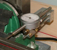
Testing the bed using a dial indicator
As with the X-axis scale, for optimum fit, we cut the Z-axis scale to a shorter length. By this time, Mike was showing real promise as a metal worker so I allowed him ;-) to tap the delicate threads in the cut off end of the scale.
Dang, he’s learnin’ this stuff a lot quicker ‘an I did!
Tapping threads in the Z-axis scale
Mike was really getting the hang of this metal working stuff. While I was away for a few days, he continued work on the project and had the Z-axis scale pretty much installed by the time I got back to his shop.
Installing the Z-axis sensor bracket
On their web site, DRO PROS includes detailed diagrams illustrating how to assemble the included mounting components.
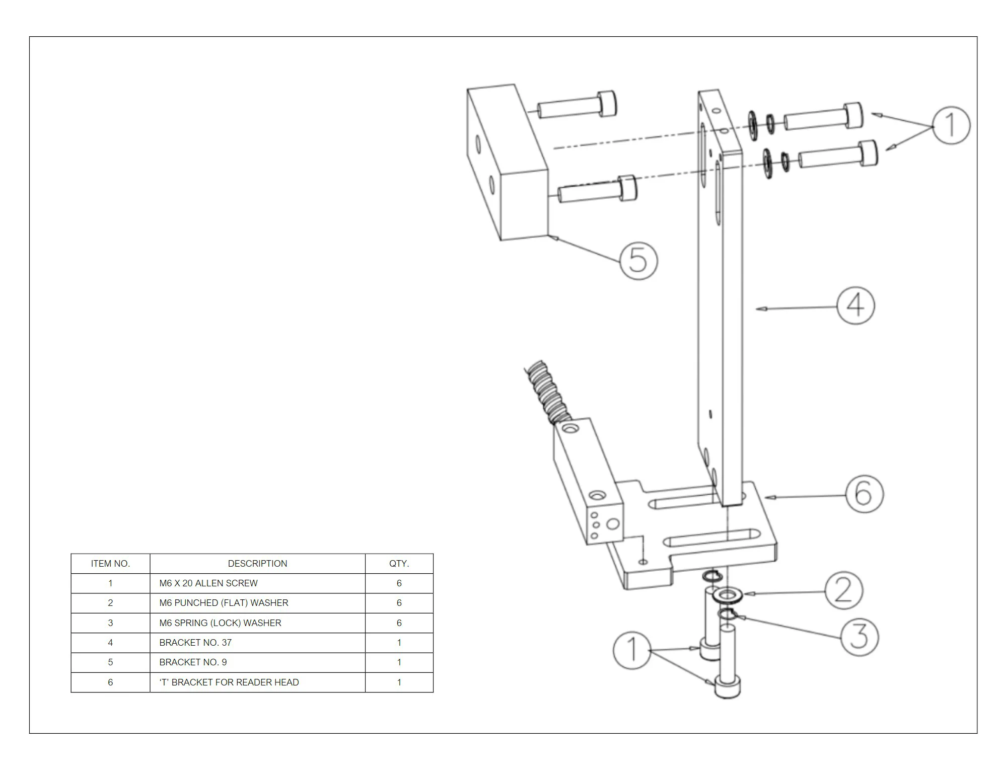
We needed to shorten the black-finished aluminum bracket that came in a kit of parts with the DRO. Mike cut it a little oversize on the bandsaw and then, using the mini mill, I milled, drilled and tapped the end.
See, we really did need the mini mill on-site!
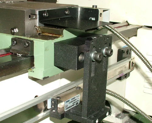
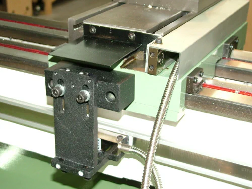
Finished mounting for Z-axis sensor
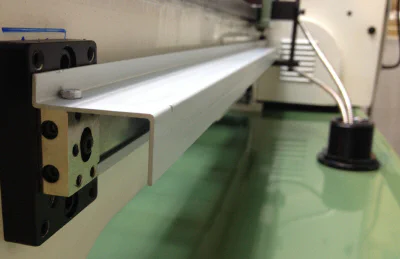
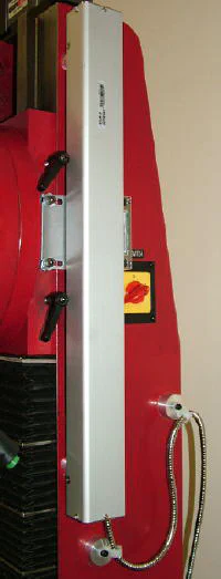
Scale with cover installed and cables routed
Final Steps
Mike continued on with some more finishing work to make the job look complete and professional. The Z-axis scale cover needed to be cut down to length and also shortened on one side.
Mike had good results using a table saw for this operation. He also devised a clever way to route the excess cable down through a hole cut in the metal tray of the lathe stand.
I’ll let him tell the story in his own words from an email he sent to me…
> Cutting the aluminum was relatively easy on the table saw. To keep from deforming the channel while cutting, I set the blade so the teeth were only 1/32" above the piece.
>
> It cut with a nice curl coming off the top of the kerf. I then cut to length on the bandsaw (that’s proving to be an exceptionally handy tool!). All edges were then relieved with some 120-grit sandpaper on a wooden block.
>
> Mounting was straight-forward. I had to shorten the cheese-head screws a bit and the lip on the cover prevented the use of washers. There is no real stress here though, so it should be OK.
>
> Next came routing the cables. I was trying to figure out a way to keep the cables out of all chips and swarf when I remembered the DRO PROS video.
>
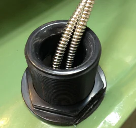
> The gun lathe they used had a coolant line that came through the chip tray. I had some old bulkhead fittings already glued-up with some 1-1/4" schedule 80 PVC.
>
> I was going to shorten them below the PVC once I cut them out and then realized the extra thickness would serve as a bearing surface for the cables as they slide in and out of the fitting… so of course I chucked it up in the lathe, surfaced the end of the fitting and shaped the inside lip of the PVC.
>
> A few minutes with some polishing cloth and the surface was as smooth as butter.
>
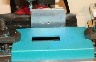
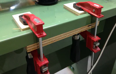
> I clamped the chip tray between some plywood for support (see the photo) and drilled the opening with a hole-saw.
>
> Normally the rubber gasket goes on the opposite side of the bulkhead fitting, but placing it under the nut helped with clearing the edge of the chip tray.
>
> Either way, it’s still sealed and if I ever do decide to use a flood coolant, there is now a convenient place to route the supply line.
>
 >
> All-in-all, I think it is a clean installation. Next step - tackling the display mount.
>
> All-in-all, I think it is a clean installation. Next step - tackling the display mount.
Looks like my hints about the display mount worked subliminally on Mike’s brain while he was sleeping.
Conclusion
This project was a lot of fun both for me and for Mike. Over the years that I’ve been working in my shop, I haven’t had many opportunities to work with a partner on a common goal.
I think Mike was appreciative of some of the tips I passed on, while I enjoyed seeing how someone else solved problems that I have worked through before on my own.
The DROs functioned perfectly from the time we first powered them on, so Mike now can get on with some true precision work. His immediate interest is making scale-model naval cannons from bronze.
In that endeavor, he gets to use both his proven woodworking skills along with his rapidly developing metalworking skills.
Just to show you that Mike’s no slouch when it comes to metalworking, here’s a model cannon he made at a course that he took in Maine a few weeks before he bought the lathe…
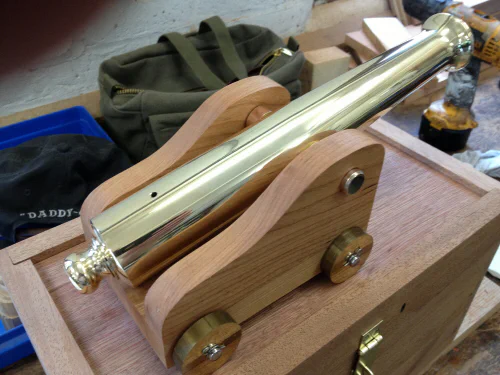
Mike’s first metal lathe project
Actually, that woodworking’s not too shabby either!!
If he’s making things that good now, I’ll be interested in seeing what he makes over the next few years - after he gets more experience. As for me, well, I’ve still got a ways to go, but I’ll get there eventually.
For more information on the DROs and the C8 lathe, check out the DRO PROS website.