SIEG Mini-Mill Power Feed
Not long after purchasing my Grizzly mini mill I started thinking about making a power feed accessory for it. While I was quite pleased with the performance of the mini mill, and excited about the new capabilities it added to my shop, making repetitive cuts several inches in length quickly became tiresome.
In my experience, Frustration, not Necessity, is the Mother of Invention, and frustration drove me to invent my own power feed solution. Although it was intended only to be a prototype, it worked so well that it has been in almost daily use for over two years now and still works like a champ.
Unfortunately, due to the unique source of the parts, it is not a design that can easily be reproduced by others. I was very pleased, therefore, to hear that Sieg has developed a standard power feed accessory for the mini mill.
Based in Shanghai, China, the Sieg factory makes virtually all of the 7x mini lathes as well as the mini mills sold by a number of U.S. and international suppliers. Among the U.S. vendors of the Sieg mini mill are Grizzly, Micro-Mark, Homier and Harbor Freight.
Besides being well made and rugged, these home shop products are very attractively priced and for many of us have made it possible to own a lathe and a mill that otherwise might forever have been financially out of reach. The addition of the power feed attachment makes the mill easier and more productive to use.
Components
Basically, the power feed accessory consists of three components:
- Power feed motor and power supply
- Replacment extra-long lead screw
- Shaft coupler
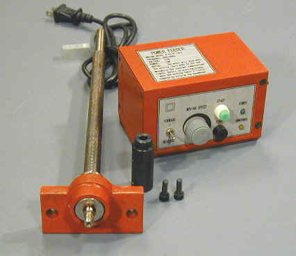
The front panel controls are as follows:
- Forward / Neutral / Reverse switch
- Speed control knob
- Reset button
- Fuse holder
- Power on pilot light (green LED)
- Overload pilot light (yellow LED labeled “UNNORMAL”)
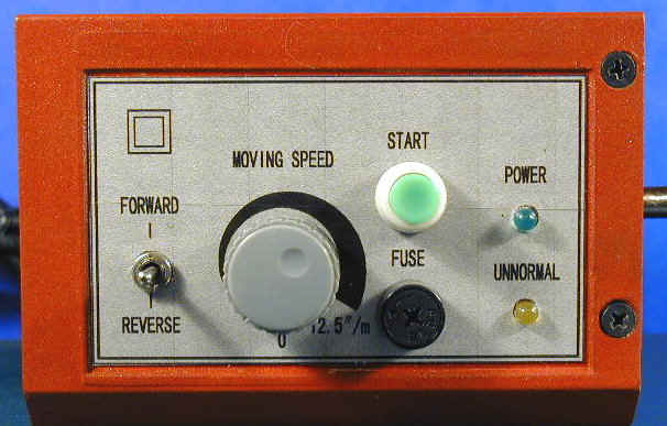
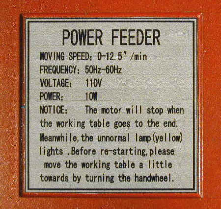
The double square above the F/R switch is non-functional, but looks like it might be reserved for some future option. On the top of the cabinet is the following label:
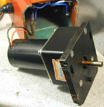
The drive motor is mounted inside the power supply housing with a drive shaft extending out the right side. The motor is a DC permanent magnet type, with an integrated speed reduction gear box. The only marking on it was a label with ‘200 RPM’ written on it.
Of a different design than the familiar variable speed power supplies used on the lathe and the mill, the speed control circuit is mounted on a small circuit board inside the housing.
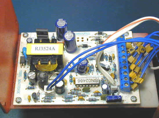
A brief, but well-written and well-illustrated instruction manual came with the power feed unit. In principle, installation is pretty simple and I expected it to take about a half hour to complete. As with many projects in the shop, though, it turned out to be not quite as simple as it first had seemed. More about this later.
Cleanup
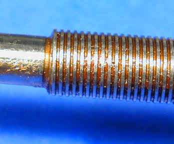
The components came individually wrapped in plastic, and the parts susceptible to rust, such as the lead screw and motor shaft, are protected by a coating of the thick red packing grease found on all of the Sieg products as shipped from the factory.
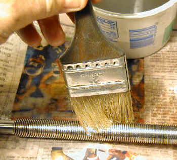
A few ounces of kerosene or WD40 and a chip brush quickly removed the packing grease.
Installing the Leadscrew
The next step is to remove the end plate and leadscrew bearing from the right end of the table. The procedure I will describe here diverges slightly from the instructions in the manual, based on my installation experience.
First crank the table all the way to the right until the leadscrew disengages from the brass nut underneath the table, next remove the two nuts that hold the handwheel in place and gently pry or tap the handle off of the end of the leadscrew.
A gear puller can be used for this purpose if you have one. Be careful not to lose the key that fits in the keyway in the shaft.
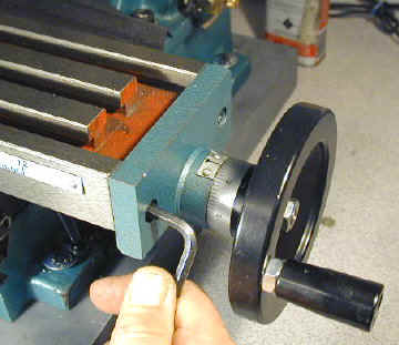
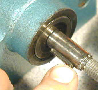
Use a hex wrench to remove the two cap screws that hold the end place in plate, then lift the leadscrew away from the table and set it aside where it will not get damaged. Besides being several inches longer than the original leadscrew, the new one is notched on the left end to receive a driving pin located in the coupling connector.
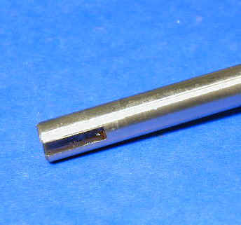
Carefully slide the new leadscrew into place so that the end passes through the brass nut under the table. When the threads begin to engage, install the handwheel on the right end of the leadscrew using the key from the other leadscrew. I found mine was pretty tight so I placed a small piece of wood across the handwheel and tapped it into place.
Advance the screw until the end plate lines up with the end of the table and then screw the end plate into position. Leave it finger tight for now, as you will need to adjust it later on.
Installing the Motor Drive
Remove the four screws from the right end of the motor housing and slide the outer shell of the housing off of the motor and the motor mounting plate. The motor is connected to the power supply by insulated connectors, and I found the installation to be a lot easier if the motor is temporarily disconnected from the power supply.
Make sure the power supply is unplugged from the AC outlet for the following step.
The motor wires are black and red, but the corresponding wires from the power supply are both blue. Mark the blue wires so that you can remember which one goes to which motor wire, then unplug the motor from the power supply. Be sure to grip the connector itself and not just the wire or you could pull the wire loose from the connector.
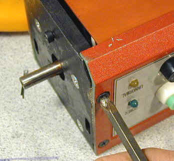
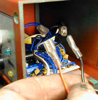
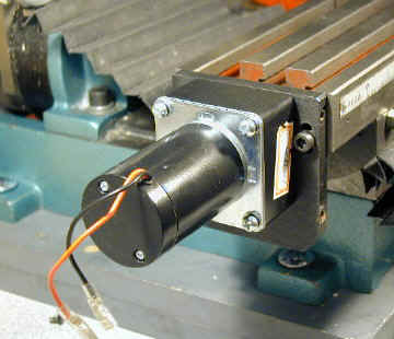
Remove the red grease from the motor shaft, then slide the coupling over the shaft such that the two set screws are aligned with the flat on the shaft. Adjust the coupling so that the end is just about even with the motor mounting plate, then tighten the two set screws down onto the flat part of the shaft to lock the coupling in place.
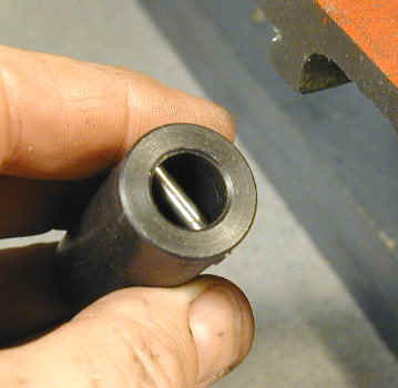
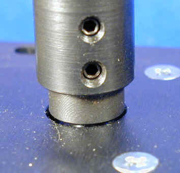
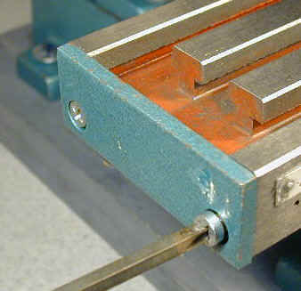
Use a Phillips head screwdriver to remove the end plate from the left side of the table. Two sides of the motor mounting plate have screw slots that line up with the tapped holes in the end of the table.
Position the motor near the left end of the table so that the coupling engages the end of the leadscrew shaft. Turn the handwheel while applying gentle pressure to the motor until the pin in the coupling engages with the slot in the end of the leadscrew shaft.
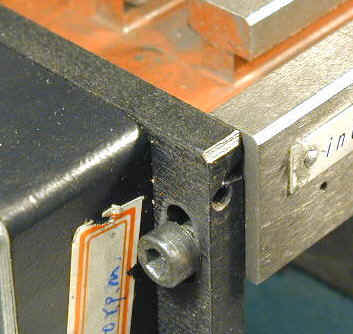
Now position the motor mounting plate so that the slots line up with the tapped holes in the end of the table and screw the motor mounting plate into position.
Alignment
It may be a problem unique to my mill, but I had a lot of trouble getting the leadscrew properly aligned so that it does not bind along the full length of its travel. This is not surpising when you consider that the leadscrew is supported at both ends and passes through a tightly fitting nut in the middle.
If all three support points are not exactly lined up, the result is binding. You can easily tell when this is happening because you can hear the power feed motor straining and can see the rotation of the handwheel slow down.
When everything is properly lined up, the speed and sound of the motor remain pretty constant throughout the full range of travel of the table.
It seemed to me that the simple way to achieve alignment would be to loosen the two set screws that lock the leadscrew nut in place (these are accessible on the right side of the mill, below the table) and then tighten down the end plates on either end of the table.
I thought that this would allow the nut to ‘float’ to the correct height, at which point I could tighten it down and be done with it. Like many theories, this one did not hold up under the rigors of actual testing.
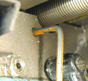
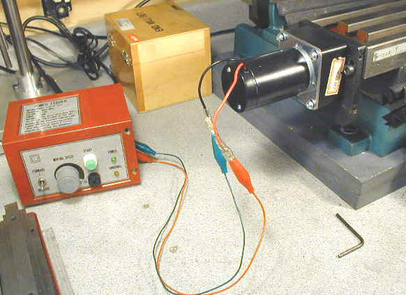
The best way (the only way, really) I found to optimize the alignment was to run the table back and forth under power and fiddle with the adjustments of both end plates and the nut until the table ran smoothly from end to end.
I used a pair of small test leads, available from Radio Shack, to connect the motor to the speed control during these tests. Make sure that the metal clips are completely covered by the soft plastic insulation so that the leads do not short out.
It really doesn’t matter which motor lead goes to which of the blue power supply leads; if they are reversed it merely changes the direction of motor rotation.
Three other variables to watch out for that can also cause binding:
- Make sure the handwheel is not overly tight
- Make sure the gibs are not overly tight
- Make sure that the X-axis lock is not restricting the movement of the table.
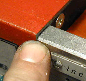
I found that the top of the motor mounting plate had to be just about even with the top of the table for best performance. Any lower than this and the lower edge coupling rubbed against the base casting.
A minor side-effect of this positioning is that the top of the cover extends above the plane of the table. If you need to mount a long workpiece that extends beyond the left end of the table you will need to raise it up on parallels so that it clears the top of the housing.

After you get the table running smoothly from end to end, unplug the power supply from the AC, disconnect the test leads and slide the housing over the motor mount. Replace the four screws that hold the housing in place and your installation is complete.
Conclusion
Rated at 12.5″ per minute, the drive speed I measured was slightly lower. My home made power feed has a top speed of around 15″ per minute and I sometimes wish it were a little faster.
12″ per minute is fast enough for most cutting operations, but when are roughing out a workpiece or just want to move the table quickly a high top speed is nice to have. Something like 18″ per minute would be nice.
As with the mill motor, you can dynamically change the speed of the power feed while it is motion by turning the speed control knob. Except for fine finishing cuts, I find that I use my power feed at top speed most of the time.
Due to the gear reduction, the motor has plenty of torque. I gripped the table by hand to simulate a heavy cutting load and it had little effect on the speed of movement.
One feature of my home made power feed not found in the Sieg design is the ability to decouple the leadscrew from the drive motor. This is very handy when you need precise hand control over the X-axis since it restores control to the way it was without the power feed.
On the Sieg unit, the load of the gear train and motor interfere somewhat with the precise manual control that you get without it. Not a big problem, but there are times when it makes a difference. Then again, it probably wouldn’t be too hard to come up with a mod to the power feed to accomplish this.
Another minor point from my own design: Maybe I’m just spatially challgenged, but I found it helpful to orient the directional switch sideways so that the switch handle points in the direction of table travel. This would be a very simple mod to make on the Sieg control panel: just loosen the nut holding the switch, twist the switch around and lock down the nut.
An overload protection feature is built into the speed control to protect the motor and electronics if the motor becomes stalled. I stalled motor intentionally a few times by running the table to the end of its limit, but the overload light did not come on.
No harm was done and when I reversed the motor direction it worked fine. When the motor is jammed like this, you may need to give it a little help by turning the handwheel to get it started.
Aside from the time required for alignment, the installation was pretty easy. As is typical of Sieg, the parts are well designed and well made. I was a little surprised that the leadscrew came with a new end plate and bearings as they appear to be identical to the original ones. By reusing the originals, perhaps the price could be me made slightly lower, although it would add a little extra work to the installation procedure.
Besides the obvious benefit of not having to wear your arm out when making long repetitive cuts, the power feed offers some additional advantages. It is a great convenience when you simply need to move the table several inches for one reason or another.
This happens all the time in my shop. Another advantage is that the drive tends to be more even that hand cranking, resulting in nice smooth finishing cuts. Having had power feed on my mill for several years now, I really can’t conceive of working without it.
Since I don’t have any information on pricing at this time, I can’t really comment on the relative value of this accessory. I think it is a very useful addition to the mill, though, and especially for those who are not inclined to try to make one of their own design (or who have better things to spend their time on!)
The best part is that a power feed accessory will soon be readily available for anyone who needs one.