LittleMachineShop.com Mini Mill
It’s been over ten years since I first wrote a comprehensive review of the mini mill back in 2002. Since that time the manufacturer has made a number of significant improvements and feature changes to this versatile home shop tool.
While the basic machine looks much the same as the older versions, the newer versions have greatly improved power, a quieter, more efficient and reliable belt-drive system plus a port for an add-on digital tach.
In this review, I’ll do an in-depth analysis of the latest version of the mini-mill as configured and sold by LittleMachineShop.com (LMS).
As regular readers of this site know, most of the mini mills and mini lathes sold by various vendors in the U.S. and worldwide are manufactured by Sieg Industrial Group in Shanghai, China.
Sieg partners with the vendors to provide custom combinations of features and color schemes so that each vendor can offer unique variations of the machines at competitive prices.
LittleMachineShop.com got its start back around 2000, as the foremost supplier of replacement parts for the mini-lathe, mini-mill and related machine tools made by Sieg.
Over the last 12 years, LMS has broadened their offerings to include a wide range of tools from top manufacturers including Starrett, Tormach and Irwin and they now sell just about everything that you might need to equip a top-quality home machine shop.
In the last few years, LMS also has started selling their own customized versions of the mini-mill and mini-lathe manufactured by Sieg. Because the mini-lathe and mini-mill are at the very core of their business focus, LMS offers a level of expertise on these tools unmatched in the industry.
Well, that’s enough background, now let’s take a detailed look at the mini-mill.
General Construction
As with most quality machine tools, the primary structural component of the mini mill is cast iron. The head, table, column and base all are made from cast iron.
Cast iron adds weight to the structure and also helps to absorb vibration; both of which contribute to a more rigid and more precise machine.
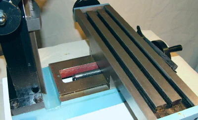
Heavy cast iron base, column and table.
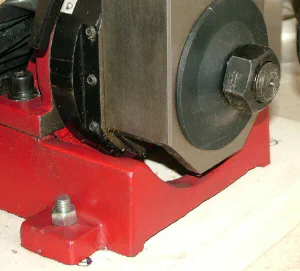
One feature unique to this LMS version of the mini mill is that the column is bolted directly to the base.
Rigid column bolted to base on LMS mini mill
What’s more, the sides of the column casting are about 40% thicker (10mm vs. 6mm) than on the standard mini mill, adding even more rigidity.
Extra-thick column walls (column cap removed for access)
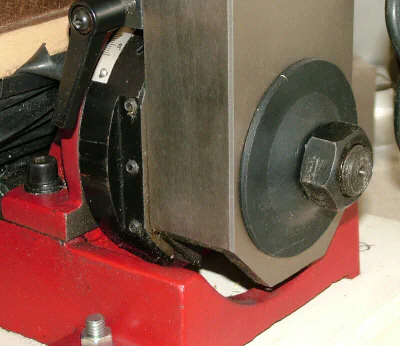
If you’ve worked with a mini mill before, or read about them on the internet, you probably know that in the standard design the column is attached to the base by a large washer and nut, allowing the column to be tilted with respect to the base.
This seems like a nice feature, since it enables the cutting tool to be set at an angle to the workpiece to cut an angled surface. In actual use, though, it’s not so convenient.
Except when near-vertical angles are involved, tilting the column shifts the position of the head far towards one end or the other of the table, thus limiting the amount of usable table space and range of X-axis table motion.
Traditional tilting-column attachment to base
When you’re done with the angled cut, you must carefully adjust the column to get it back in an exactly vertical alignment - a procedure called tramming - that takes time and some trial and error.
And there’s always the risk that the column may shift at some future time due to strong cutting forces or accidental impact, causing inaccuracies in the cut and possible damage to the workpiece.
If the shift is small enough that it’s not noticed, it may cause all future cuts to be out of square until it is discovered and corrected.
Therefore, LMS collaborated with the Sieg engineers to develop this rigid-column model of the mini mill.
I’ve worked with several mini mills over the last ten years and in my experience, LMS made the right choice on this feature. For most situations where you need to make an angled cut, it’s more practical and easier to tilt the workpiece rather than the column.
This can be done by holding the workpiece in a or by using a tilting table or sine plate.
Recognizing that there are some prospective owners who still prefer the tilting column capability, LMS also offers a tilting-column version as Item #3900.
There are, apparently, some operations that can be done with the tilting column feature but not with a tilting vise - I’ve just never run into such a situation in my shop.
Accessories
As you unpack your LMS mini mill, you’ll find a plastic bag filled with parts and tools, including a set of metric open-end wrenches and hex wrenches for adjusting the mill.
The other parts include the draw bar, handles for the table handwheels, drill chuck arbor, plastic oil bottle, spindle stop and two T-nuts.
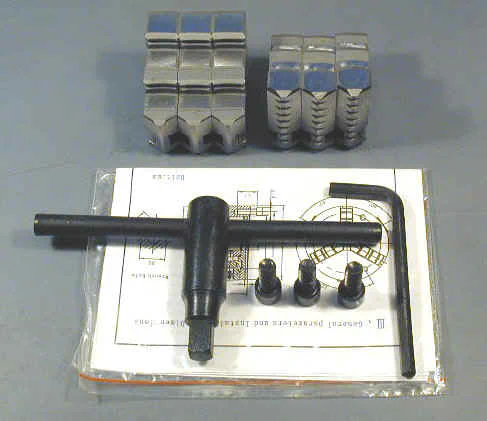
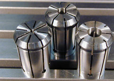
Accessories included with the mini mill
One accessory that you’ll need right away is a drill chuck. LMS offers a range of chucks so that you can select one that meets your cost and precision requirements.
Be sure to order a chuck with a taper that matches the included #33 Jacobs Taper (JT) spindle, though.
There are several other accessories that you should plan to purchase at the same time as your mill. You can find some of my recommendations on the Mini Mill Accessories page.
LMS has a complete range of accessories available and provides a lot of useful tips on their web site to help you select the items you need to get started.
Prior to starting up LMS, Chris Wood, the founder, was a full-time technical writer. Not surprisingly, then, Chris wrote the 32-page user manual for the LMS mini mill.
The manual is thorough, well-written and illustrated with clear photographs and diagrams.
Beyond the standard operating procedures, you’ll also find some tips, such as how to square a milling vise, how to use parallels and how to locate the edge of a workpiece - all things you’ll need to know to get started using your mini mill.
Here’s an example:

Motor and Drive Train
The LMS mini-mill has the powerful 500-watt high-torque brushless DC motor. Highly efficient, this motor runs cool enough that it needs no ventilation holes or fan.
Therefore, it’s completely sealed from dust, dirt, oil and shop swarf - a feature that will likely mean a very long working lifetime.
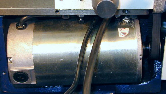
500-Watt Brushless DC motor
These motors also run very quietly and are silent when stopped, since no cooling fan is needed in the motor or in the speed controller.
Such quiet operation is a real benefit if your shop is in a spare bedroom (or maybe your main bedroom ?!) and you’re working late into the night while others in the household are sleeping (Like normal people. When I was younger, I often used to work in my shop until 1 or 2 AM.)
If you’d like to learn more about how brushless motors differ from conventional DC motors, the basics are covered in this Wikipedia article.
Though only about half the size and weight of its predecessor, this little motor packs a lot more punch.
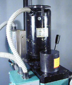
Classic style motor on early mini mill from 2000
The earlier motors have plenty of power at high speed, but have limited torque at lower RPMs, requiring a gearbox in the head assembly to reduce the spindle speed and provide more torque.
In the older design, virtually all milling operations were done in low range; the high range being used mainly for drilling small diameter (< 1/8") holes that require high RPMs.
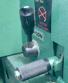
HI-LO gear range selector on classic model mini-mill
A disadvantage of the earlier design is that the gear teeth between the motor and spindle could easily be broken if the cutting tool was advanced too aggressively into the workpiece.
Not that it ever happened to me, of course, but I will admit to keeping several sets of spare gears on hand at all times, “just in case.” ;-)
In the LMS mini-mill, there are no gears to worry about; the spindle is driven by a toothed belt from the motor. Not only is this design more efficient in transferring power to the spindle, it’s more reliable and quieter since there’s no gear train inside the head.
The HI-LO gear range lever is gone and the full range of speeds is controlled directly from the motor speed control knob. Overall, it’s just a much better setup than the original.
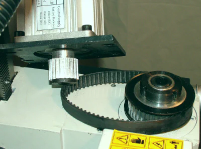
Drive cover removed to show direct belt drive
A trade-off for the brushless motor is that both the motor and the electronics required to drive it are more complex and expensive than for a conventional DC motor.
In a brushless motor, the phase of the magnetic field is controlled by electronic switching rather than by mechanical brushes.
But, while the new speed controllers are more complex, they are excellent in quality, and, in my experience over the last few years, have been very reliable.
Mounted in a separate box on the back side of the column, the controller board is well-protected from chips and fluids. Screened vent holes provide for convective air flow.
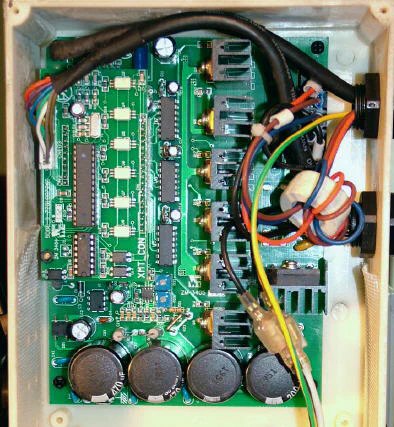
Controller board for brushless DC motor
Cables between the controller box and the motor and front panel are well-protected by rugged flexible plastic cable shields.
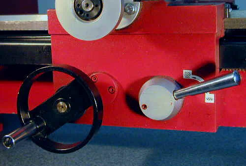
Flexible plastic cable shields
Electronic Controls
All of the electronic controls are located on a small box mounted on the left side of the head.
- Power On/Off switch and Emergency Stop
- Fault indicator lamp
- Power pilot lamp
- Speed control
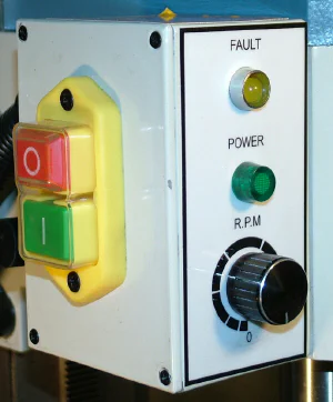
Control box on left side of mill head
The mini mill plugs into a standard 15- or 20-amp 120V outlet. Power is turned on by pressing the large green button on the side of the box and turned off by pressing the red button.
The red button also serves as an emergency stop button. It’s large and sticks out farther than the On button so that you can quickly mash down on it if something’s not right.
A thick clear plastic membrane covers the switches to keep out contaminants. On most versions of the mini-mill that I have used, the switches are enclosed by a hinged cover, but the cover is not present on this one, making the buttons more easily accessible.

Power OFF & ON buttons
Rotational speed for the spindle is set by turning the speed control knob, providing a continuously variable range of speeds from zero to about 2,500 RPM.
Continuously variable speed control really sets these machines apart from more traditional mills that require you stop the spindle and move belts between different sets of pulleys to select one of a few (usually six) fixed speeds.
On the mini-mill, you can change speeds between operations without stopping the motor, as for example to set a higher speed to make a shallow finishing cut on the workpiece - a great convenience and a great time saver.
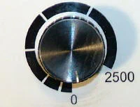
Speed control knob
It’s good practice always to turn the speed control knob to zero before stopping the mill. That way, when the mill is powered back on, the spindle will remain stopped until the speed control knob is advanced to the desired working speed.
On some previous models of the mini mill and mini lathe, that discipline was enforced by a switch built into the speed control knob, but the switch is not present on this model.
As on all the newer Sieg machines that have the brushless DC motors, the motor speed control is intelligent.
If the motor becomes overloaded or stalled, the speed controller shuts off power to the motor, to protect it from overheating, and illuminates the Fault LED.
When a fault occurs, an internal relay is tripped, cutting off power to the motor. Once the condition causing the stall is cleared, the speed control is reset by pressing the green ON button.
The controller also provides electronic braking for the motor, bringing it rapidly to a stop when the speed control is turned to zero or the red Stop button is pressed.
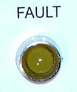
Yellow fault LED
The internal relay also trips if power to the mill is interrupted by a tripped circuit breaker or power failure. This feature ensures that the mill will not start back up unexpectedly when power is restored. On the subject of power failures, I recommend having one or more emergency lights in your shop so that you aren’t left in the dark - possibly with a cutting tool spinning in the spindle - if a power failure occurs while you’re working.
The Fault Indicator lamp illuminates if the motor stalls from taking too deep a cut. The power supply senses when it is overloaded, and shuts down. To restart the mill, the green On button must be pressed.
On the back side of the control box are located the fuse holder and the plug-in port for the optional digital tachometer. When not in use, the port is covered by a plastic cap to keep out dirt, chips and shop fluids.
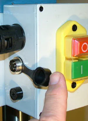
Tachometer port and fuse holder on back side of control box
In the early models (before 2005) of the mini mill and lathe stalling the motor by taking too deep a cut often would blow the fuse. Due to the much improved motor controllers in use now, I haven’t blown a fuse in years.
Digital Tachometer Option
An optional digital tachometer is available (# 3818) for those who like to know exactly how fast the spindle is turning.
The tach plugs into a port on the back side of the control box and attaches magnetically to a metal plate at the top rear edge of the control box. It displays the current spindle speed to within the nearest 10 RPM, which is precise enough for any type or work that you’ll do on this mill.
While nice to have, it’s not really essential, and can certainly be deferred to a later purchase date if funds are limited.
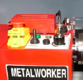
Tach plugged into tach port
When in use, the tachometer display plugs into the port and the connectors are secured by a threaded shroud. Magnets on the back of the tach housing hold the tach to a metal plate attached to the back of the control box.
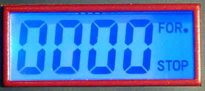
Spindle rotational speed is displayed rounded to the nearest 10 RPM. The backlit LCD display is easily readable from several feet away.
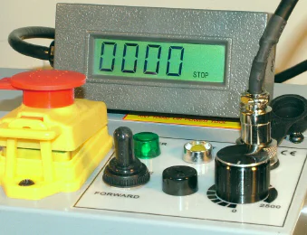
Digital tach display
Note: the display shown in the photo is from an earlier mini mill and may differ slightly in appearance from current models.
Table
The cast iron table is strong and heavy. It is longer and wider than the table on the standard mini mill and has longer travel in both the X- and Y- axes.
| Table Length | Table Width | Table X-axis Travel | Table Y-axis Travel | |
|---|---|---|---|---|
| LMS Mini Mill #3960 | 18.1" (460 mm) | 4.7" (120 mm) | 11.8" (300 mm) | 5.1" (130 mm) |
| Classic Mini Mill | 15.1" (380 mm) | 3.9" (100 mm) | 9" (230 mm) | 4" (100 mm) |
The extra table size and range is a real advantage as I often have run into situations with the standard table where I had to mill part of a workpiece, then re-mount it at a different position on the table to complete the operation.
Naturally, Murphy’s law ensures that no matter how big a table you have, you’ll soon have a job that is just a little too big for it. Of course you won’t discover that the workpiece is too big until you’re cutting along happily and then suddenly run up against the end limit of the table.
A few years ago, a target-shooting buddy of mine, who is amazingly skilled at repairing antique guns, and even building them from scratch, used a mini mill to mill the sides of a round rifle barrel to convert it to an octagonal barrel.
Because the barrel was quite a lot longer than the table of the mini mill, he had to make several passes on each side of the octagon, carefully aligning the barrel with a dial indicator to ensure that the cuts were even along each side.
The finished result is so well done that you would never guess that it could have been done on a mini mill. So, with skill and perseverance, even Murphy sometimes can be defeated, or at least fooled for a while.
A power feed accessory for the X-axis is a great addition to any mini mill, but is especially helpful on this mill due to the longer table length.
With the power feed in operation, instead of wailing away on the X-axis handwheel, you can sit back in comfort and watch the power feed do all the work.
The power feed kit is available separately from LMS as item #4211. If funds are limited, this accessory makes a good future upgrade.
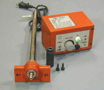
Add-on X-axis power feed kit.
Not only is it quicker and a lot less hassle when cutting a long workpiece, but the finish will be smoother due to the even speed of the power feed. If you’re adventurous and have the time, you can make one from salvaged parts.
Head and Spindle
Coarse Control
In addition to milling operations, the mini mill serves as an excellent precision drill press. Key to this dual functionality is the rack-and-pinion drive mechanism.
A 3-spoke handwheel, like you’d find on a drill press, provides coarse motion of the head up and down the column.
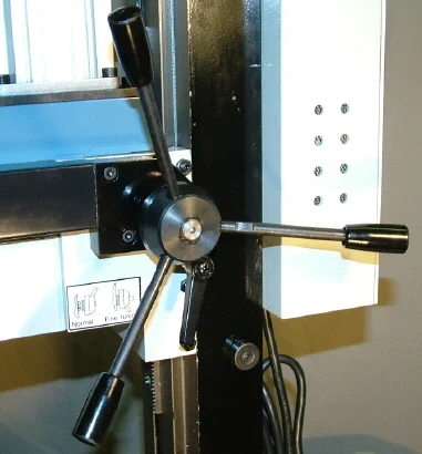
3-spoke handwheel controls coarse head movement
On a drill press, and every other milling machine that I’m familiar with, the handwheel moves the spindle in and out of the head over a limited range, typically of 3-4 inches, depending on the size of the machine.
By contrast, on the mini mill the handwheel can move the head over the full range of the column - about 10" (25 cm).
That extra range of motion can be very helpful when drilling deep holes with larger diameter drills, but the real benefit is being able to quickly and easily move the head clear of the work area for changing drill bits or end mills.
Fine Control
For milling operations, cutting tool depth needs to be adjustable to within one one-thousandth of an inch (0.001", .025mm) or better for precision work. A fine-feed control knob on the right side of the head is used for this purpose.
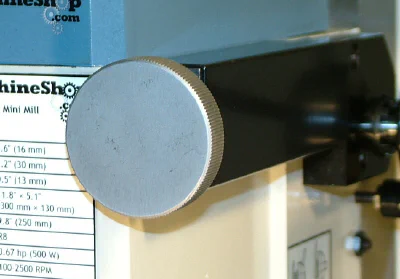
Fine-feed control knob
Fine-control (“fine tuning”) is activated by pushing inwards on the 3-spoke handwheel to engage a pair of castellated gears.
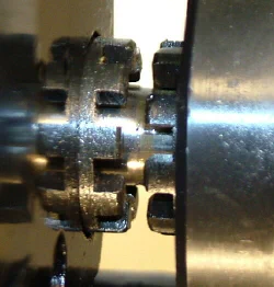
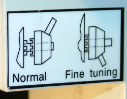
A rotating ring, calibrated in units of 0.001" measures the depth of the cut and can be set to zero by grasping the handwheel while turning the knurled grip on the calibrated ring.
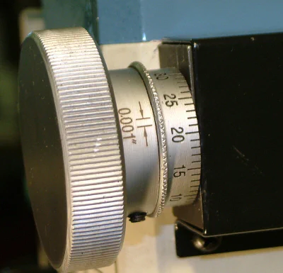
Calibrated fine-feed depth control
A tradeoff of this arrangement is that there’s quite a lot (~0.020-0.040") of backlash in the fine-feed knob. While this at first may seem daunting, you soon develop the habit of always starting the downward movement of the head above the desired end-point.
As the knob is turned to move the head down, the backlash is taken up and readings on the scale from that point on are accurate.
An even better solution, and one that I enthusiastically recommend, is to install a vertical digital readout (DRO) on the side of the mill. With careful use of the DRO, you always know the exact depth of your cut.
Here’s a photo of one installed on another mini mill.
After-market DRO installed on a mini mill
As a bonus, the DRO is easy to read and lets you switch between inch and metric units at the touch of a button.
Torsion Spring Arm
Common to all of the mini mills that I’ve reviewed since around 2002, this one uses a coil spring to offset the weight of the head.
As the head is lowered, the spring, enclosed in a cylindrical housing, is wound tighter, absorbing the downward force of the heavy head.
As the head is raised, the spring unwinds, offsetting the weight of the head to make it easier to move upwards.
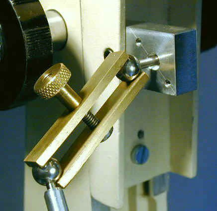
Torsion arm on left side of column
A gib strip along the back right side of the head also helps control the movement of the head by providing friction between the head and the column.
If you’re new to machine tools, a gib is a length of metal with a diamond-shaped cross section, typically made from soft steel, brass or bronze.
The strip fits snugly into the dovetail slide and can be adjusted to take up any slack caused by wear over a period of months or years.
When properly adjusted, the gib minimizes any play in the dovetail slide while still allowing free movement of the slide. For smooth motion and to prevent excessive wear, the dovetails should always be well lubricated with oil or light grease.
I used to recommend white lithium grease for this purpose, but later switched to using oil because WLG tends to dry out and become less effective over periods of a year or more.
Early models of the mill used a compressed-air spring piston to offset the weight of the head. My first mini mill from Grizzly came with the air spring.
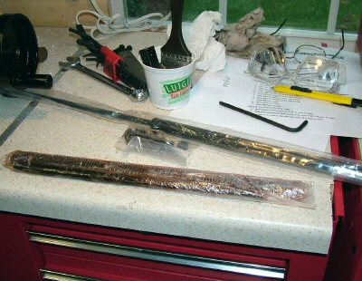
Air spring on 2000-model-year Grizzly
Personally, I like the air spring better than the torsion spring. It gives a more even supporting force over the range of movement of the head and provides an extra 1 1/4 inches (31 mm) of movement at the top of the column.
For those who prefer it, you can buy an air spring conversion kit from LittleMachineShop.com to replace the torsion arm.
During any machining operation, the head must be securely locked to the column by tightening the locking lever behind the 3-spoke
Spindle & Chuck
The mini mill makes such a handy drill press that I find it quicker to use it rather than the drill press in my shop, as long as the workpiece is not too large for the mini mill.
Most of the time, I have marked the location for the hole using layout dye and a height gage, so it’s really convenient to clamp the workpiece in the milling vise and use the X- and Y- handwheels to line up the workpiece under the spindle.
If the location of the hole needs to be precise, which is true for most of the work I do, I first mount a sharp pointed tip in the drill chuck and align the tip with the cross-mark where the hole is to be centered.
For best accuracy I often use a flip-up magnifying headband when lining the tip up with the layout marks. Next, I replace the locating tip with a center drill and center drill the hole to make a good starting hole for the drill bit.
If the hole is small diameter and not very deep, I will then drill the hole with the final size drill bit, but it’s often good practice to use two or more drills of increasing diameter to reach the final required diameter.
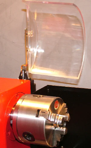
Setup and Cleanup
Regular readers and experienced users know that all Sieg products are liberally coated with a layer of soft red grease that protects the bare metal surfaces, such as the table surface, column and chuck, from rusting during transport and storage.
The grease is easily removed with some old rags, paper towels and kerosene or WD40. Experience has taught me that its easier to do this job after the machine is at bench height, rather than while sitting on the floor.
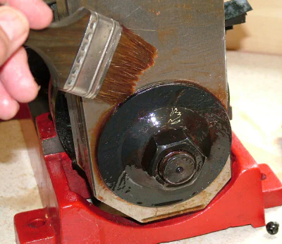
Cleaning up the shipping grease with kerosene
Conclusion
With thousands now in operation around the world, the mini lathe is a proven tool for the home shop machinist. The basic design is sound, and the areas that have been troublesome, such as the drive gears, have steadily been improved or eliminated by the manufacturer.
The result is a very effective machine that can perform many metal-cutting operations that would be difficult or impossible to do any other way in the home shop.
LMS now has taken this improvement trend even farther by offering a rigid column option along with a longer table.
The fixed column ensures maximum rigidity, for optimal cutting, while ensuring that the cutting tool remains properly aligned with the table and does not shift during heavy cutting operations.
While the longer table doesn’t make the LMS mini mill into a Bridgeport, it’s sure to help in those situations where the work is just a little beyond the range of motion of the standard table.