DROs for SX4
The Sieg SX4 is a very capable mill, but to use it to its full potential, digital readouts (DROs) are needed.
On the Super X3, I used low-cost digital scales for the distance measuring elements and employed a two-axis LED readout.
While that installation worked well, for the SX4 I decided to use commercial DROs from Shars Tool made specifically for milling machines, lathes and other machine tools.
They are available in both 2-axis and 3-axis versions and in size ranges that will fit just about any mill. Because the SX4 has a built-in DRO for the quill, I could get by with just a 2-axis kit, but I knew that there might be projects in the future for which I needed to use more than just the 3 1/2" range of the quill.
Therefore, I decided to go with a 3-axis kit and have a scale for the full range of the Z-axis.
These scales use a more precise technology than the low-cost DROs and are accurate to 0.0001" (a ten thousandth) or better.
Of course, there are many variables that affect the final accuracy of the work, such as play in the dovetails and runout in the spindle of the mill, but these scales will let you measure accurately to the limits of precision that the SX4 is capable of.
Packaging
The DRO kit arrived promptly from Shars and was securely packaged in two boxes. Everything inside was in perfect condition.
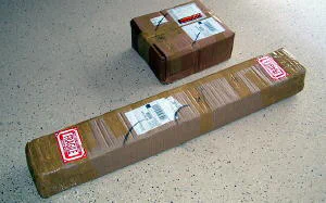 Shipping boxes received from Shars Tool
Inside the boxes, the kit for each axis is packaged separately. Each kit includes a package of screws, shims, and other parts to facilitate mounting of the DROs.
Another kit of heavy-duty cast aluminum flat and “L” brackets provides an Erector-Set of options for tricky mounting situations.
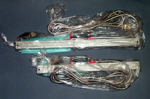 DRO kits for two of the axes
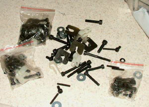 Packages of mounting hardware
 Cast aluminum brackets
The sensors are secured to the scale for shipping by a red plastic retainer. I kept the retainers in place during much of the trial positioning of the sensors to reduce the risk of damaging the internal scales.
When ready to mount the sensor, the retainer screws are removed and the retainers gently pulled out from the scale.
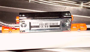 Sensor held in place by retainers
X-Axis Installation
Because it looked like the most straightforward installation of the three axes, I decided to tackle the X-axis first. The X-axis scale in the kit I selected is 30 inches long and is a good fit for mounting directly on the back edge of the table.
Depending on the configuration of each axis, you must decide whether the scale will be fixed and the sensor will move or the sensor will be fixed and the scale will move.
Because the cable attaches to the sensor, where it was feasible, I decided to make the scale moveable and the sensor fixed to reduce wear and tear on the cable - and the potential for it to get snagged on something.
The first order of business was to do some trial positioning of the scale and scale cover to see how it would fit. On the back side of the SX4 table, at either end, are located threaded steel plugs about 1 1/4" in diameter.
These are access holes for installing an optional coolant pump system. I have never used coolant with the mills I’ve had up until now, but due to the larger capacity of the SX4, I anticipated that I might want to use it in the future.
Therefore, I wanted to mount the scale without interfering with the access holes. That was the plan, at least.
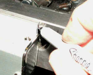 Marking locations for the scale cover
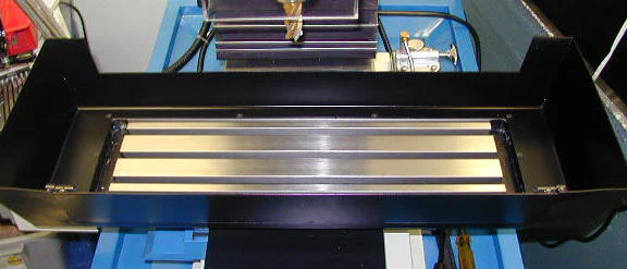
As it turned out, the cover for the X-axis scale was long enough so that at least one of the access holes would be partly or completely overlapped by the scale cover.
Therefore, I decided to mount the scale and cover a little off-center to keep the access hole on the left end of the table accessible for future use. Unfortunately, I seem to have lost track of that little detail somewhere along the line, and ended up with both holes partially covered by the scale cover.
Not a big deal, really, since it can easily be fixed when/if I need to use the ports, but just an annoyance. And an embarrassment, now published for all the world to see.
I wanted to make sure that the top edge of the scale cover was below the level of the table so that it would not be in the way of workpieces, vises, or other holding devices that extend beyond the back edge of the table.
Once that level was established, the location of the scale was determined. To make sure everything was ok before I started drilling holes in the table, I first mounted the scale to the table using some quick-drying glue.
This has proven to be a useful technique on a number of projects and has helped me to avoid some positioning errors that were not at first apparent. With the scale thus tacked in place, I moved the table through its full range of motion to make sure that there were no surprises.
None being found, I gently prised the scale free from the glue and cleaned up the glue residue with some naptha (lighter fluid).
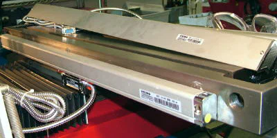 X-axis scale tacked in place with glue
With the hole locations marked out, I center-punched each hole and then started the hole using a center drill to help ensure that the hole is drilled in exactly the right location.
My experience with drilling cast iron when using a hand-held drill is that the drill bit tends to wander away from where you want it, with the hole ending up not exactly where it should be.
In a perfect world, I would remove the table from the mill and drill the mounting holes on a drill press. But with a table as heavy as this one, that did not seem like a practical approach, so I had to use a hand drill.
Cast iron is pretty tough to drill, so I selected an AC powered drill rather than a rechargeable battery-powered one.
Be sure to vacuum up any cast iron dust after completing your work as it can cause excessive wear on dovetails and other moving parts.
 Center-punching the marked hole location
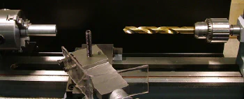 Center-drilling the hole location
Since these holes have to be tapped, I used a small shop-made depth gage to make sure that each hole was deep enough for the tap - since the tip of the tap is tapered and does not cut full threads.
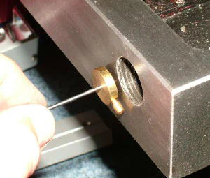 Testing hole depth with a depth gage
When tapping the holes, I used a shop-made tap guide to ensure that the tap is perpendicular to the table surface. In use, the tap guide is supported by my left hand while I turn the tap wrench with my right.
Properly used, the guide will also help support the tap to reduce the risk of the weight of the tap wrench breaking the tap off in the hole. Due to the tight confines, a ratcheting tap wrench is useful here.
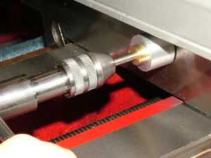 Using a tap guide to ensure tap is perpendicular
I used a gentle (low pressure) blast of compressed air to clear chips and residue from the tapped holes. Be sure to wear eye protection with side shields if you choose to use this method.
Some machinists frown on the use of compressed on machine tools as it can drive chips and grit into inaccessible places where it can cause wear, so take appropriate precautions to prevent this.
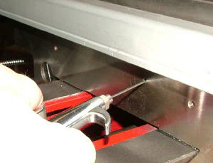 Blowing out the chips using compressed air
The scale is mounted using 4mm cap head screws provided in the hardware kit. Several lengths of bolts are included to accommodate variations in mounting requirements specific to each style of machine.
After the scale is loosely bolted in place, a dial indicator is used to ensure that the scale is parallel to the surface of the table.
The next step is to mount the sensor to the Y-axis casting. The Y-axis casting supports the table and remains fixed in position relative to the X-axis when the table is moved.
Therefore, the sensor remains in a fixed position while the scale mounted on the back edge of the table moves past the sensor.
I find accurately positioning holes in cast iron to be notoriously difficult when using a hand-held drill. After the scale was secured in place I used a transfer punch through the mounting holes in the sensor to accurately mark the hole locations for the sensor on the back edge of the Y-axis casting.
Then I tapped the holes. Unfortunately, I found the holes to be off position by just a very small amount, but enough in this case so that they would not work.
Unlike the scales, which have oversized elongated mounting holes and can accommodate small errors in the screw hole locations, the sensor holes are just large enough for a 4 mm bolt to pass through.
If the corresponding mounting holes are not in exactly the right place, the screws won’t line up.
One option would be to drill and tap a new set of mounting holes offset from the first set by a centimeter or so. But then I would run the risk of just repeating the same problem in a new location.
Instead, I decided to use a solution that has worked well for me in similar situations in past projects: just glue a mounting plate to the casting. First I used some feeler gages to determine the spacing between the back side of the sensor and the mounting surface.
A short scrounging session in one of my scrap boxes located some candidate pieces of scrap of the right thickness; then I just rough cut the piece on the bandsaw and finished the edges on the belt sander.
There are two types of glue that I use for this kind of application: super glue and Quick Grip. In this case I decided to go with super glue. I placed a few drops on one side of the plate and held it position for about a minute while the glue set.
Then I place a few drops on the front side, slid the sensor over the plate and held the sensor against the plate for about a minute. Quick, simple and it does the job with a lot less time, effort, dust and potential for error that drilling and tapping would entail.
If it ever becomes necessary to remove it, the plate can be pried off gently using a small wood chisel.
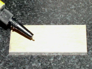 A few drops of super glue for the mounting plate
The final step was to cut out a notch in the fiberglass frame that holds the accordion-style chip shield to the Y-axis casting.
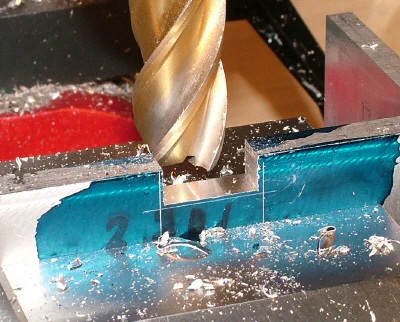
I marked the edges of the sensor on the frame, then held the frame in the milling vise and milled out a rectangular window to accommodate the sensor.
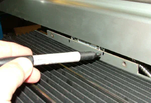 Marking the section to be cut out
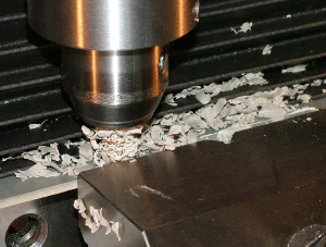 Milling a slot for the sensor
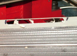 Finished (well, nearly) slot
I had to leave a thin strip of material near the top of the slot so that the milling tool did not hit the jaw of the vise that was holding the work. The strip was clipped off using a pair of wire cutters, then smoothed with a file.
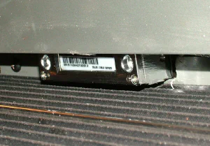 The sensor with the chip shield back in place
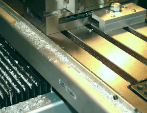 Scale with chip cover in place (and chips!)
Z-Axis Installation
A nice feature of the SX4, and the other Sieg mills, is the dovetail column. One advantage of the dovetail column, not shared by round-column mills, is that the X and Y position of the head with respect to the work remains fixed as the head is raised or lowered.
Therefore, if you happen to have a workpiece, such as a casting, that requires cutting in the Z-axis to depths that are greater than the range of the quill, you can move the head up and down the column instead of, or together with, moving the quill.
But if you do that, you can no longer rely only on the quill DRO readout for measuring the depth of your cut. Hence the advantage of having a DRO for the full Z-axis range.
Continuing with my plan to leave the Y-axis for last, I proceeded with the Z-axis installation. Just to illustrate some of the choices you have to make during this process, I concluded that the easiest approach for the Z-axis would be to secure the sensor to the head and fix the scale to the column.
On this axis, the scale is relatively exposed, so I felt safer having is securely attached to the column rather than moving up and down with the head.
It also looked like it would be easy to mount the sensor to the head, but complicated to mount the scale.
I marked out, drilled and tapped mounting holes for the scale. This procedure was pretty easy and went quickly.
Unlike the scale for the X-axis, which mounts directly to the machine, the Y- and Z-axes include mounting brackets to support the scale; especially in situations where the scale will be moving and extra rigidity is called for.
While the chip shield for the X-axis mounts directly to the machine, the chip shields for the Y- and Z-axes mount to the support bracket. In the photo below, I’m marking out the mounting holes for the support bracket.
The scale will then be bolted to the bracket.
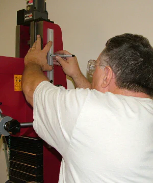 Marking out the hole locations for the mounting bracket
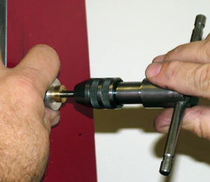 Mounting holes for the bracket are drilled and tapped
The obvious approach was to mount the sensor in the space on the head between the two locking levers; so that’s what I did. Included with the mounting hardware are a number of flat and “L” brackets pre-drilled and tapped with mounting holes.
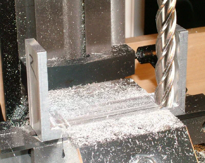
I selected a flat bracket and then cut and milled it to the size I needed. I milled a shallow ledge where the bracket will move up and down against the column to prevent the bracket from rubbing against the column.
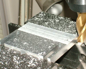 Milling the clearance ledge
I decided to use 1/4-20 cap head screws to secure the bracket to the head. They were just a little oversize in diameter for the slots in the bracket, so I milled the slots out to 1/4" width.
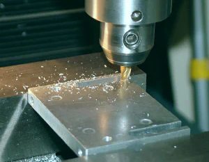 Milling the slots out to 1/4" width
Now, with the sensor bracket in place, as specified in the instruction manual, I used a dial indicator to ensure that the scale was parallel to the movement of the head.
With the tip of the indicator lined up on the raised lip of the mounting bracket (the DI couldn’t reach to the back edge) I ran the head up and down a few times, adjusting the mounting bracket until there was less than .
002" runout. Absolute precision is not necessary, so this was close enough.
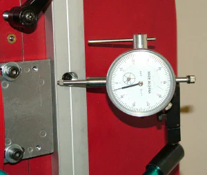 Using a dial indicator to check alignment
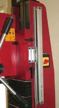 Z-axis scale and sensor mounting (first attempt)
While this arrangement was relatively easy to install, and worked well, it has the disadvantage of exposing the underside of the scale to flying chips.
Rubber windshield-wiper-like seals help to keep any chips from the insides of the scale, but the installation manual is pretty clear that this type of exposure must be avoided.
Therefore, I decided to bite the bullet and do it over - correctly this time.
Doing it correctly was a little more challenging. I would need to flip the scale over so that the open side was towards the back of the mill. This means that sensor would also be on the back side of scale, but would still need to be attached to the head.
After a little creative thinking, I decided to add spacers to the scale mounting so that the bracket supporting the sensor could pass underneath the scale.
A trial placement of the scale at the front edge of the column revealed that the scale would extend a little bit over the black steel plate surrounding the power switch.
Therefore, washers were needed under the sensor mounting plate and the spacers would need to be thick enough to allow the sensor mounting plate to pass over the power switch mounting plate and the screws holding it in place, which worked out to about 0.650".
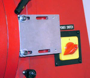 The sensor plate must clear the power switch mount
The brackets provided with the scale, unless two more were stacked together, did not provide enough thickness for what I now needed to do, so I decided to machine a few round spacers on the lathe.
I had some 7/8" diameter aluminum bar on hand and could easily make a couple of spacers as thick as needed.
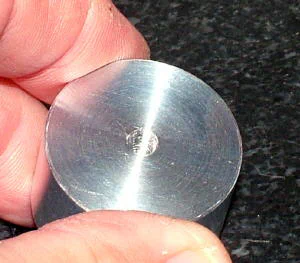 Lathe-made 7/8" diameter spacer with 10-32 tapped hole
The plan was to glue these spacers in place only for prototyping the layout, then replace them with permanent spacers once the layout of all of the components was determined.
I used Quick Grip glue, from the crafts department at Wal-Mart as the glue of choice for this work.
Quick Grip, as its name suggests, quickly forms a strong grip, making it great for prototyping where you don’t want to wait very long for glue to dry, but can be disassembled and cleaned off using a little naptha.
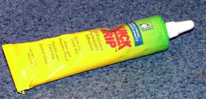 A little Quick Grip glue to hold the spacer in place
After mounting the top spacer to the mill and waiting about 15 minutes for the glue to dry, I mounted the scale and the lower spacer. Then I repeated the alignment procedure with the dial indicator before the glue on the lower spacer set completely.
This allowed me to let it set with the scale properly aligned. I then made two more similar spacers to hold cable clamps, but selected clamps that were a little oversize so that the cable could slide through the loop of the cable tie.
This arrangement lets a short loop of cable form as the head is lowered, and retract as the head is raised.
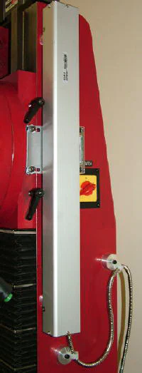 Z-axis scale in place with cable supports and good chip shielding
Y-Axis Installation
Due to its less accessible location, the Y-axis installation is the most difficult of the three. I had to remove the power feed to provide better access and found that a sitting position was more comfortable for working on this axis.
After playing around for a while with the various brackets that came with the DRO kit, it became apparent that some standard aluminum L-bracket that I had on hand would be a good fit for what I needed to do.
I decided to mount the sensor fixed to the base of the mill and mount the scale on the side of the Y-axis casting so that it moves past the sensor as the Y-axis is moved.
This arrangement avoids having the cable moving along with the Y-axis. A little drilling and milling and I soon had a pair of brackets that join together in a Z-configuration, as viewed from the end.
I milled elongated holes to allow for adjustment of the DRO to make it parallel to the X- and Y- axes of the mill. The DRO support beam that came in the kit of parts with the DRO supports the DRO scale for extra protection and stiffness.
 Bracket 1 to mount on side of Y-axis casting
 Bracket 2 mounted to DRO support beam
 Other side of DRO support beam
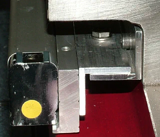 Here’s an end view showing how the two L-brackets work together
 And a side view of the finished mounting
After assembling the brackets and mounting them to the Y-axis casting, I then used a dial indicator to align the scale to be parallel with the X-and Y axes.
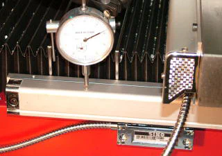 Using a dial indicator to align the scale
As with the X-axis, I used a few small drops of superglue to glue a small spacer plate between the sensor and the base of the mill where it attaches. The spacer takes up the small gap between the back of the sensor and the side of the mill base.
It can easily be popped loose for maintenance, if required, by prying gently with a the blade of a sharp wood chisel.
The side of the base casting is not strictly vertical but slopes inward slightly from bottom to top about a ten-degree angle. There are small set screws provided with the sensor units that can be used to adjust for such angles.
They simply screw into the housing of the sensor and out through the back side where they press against whatever the sensor is mounted to, the spacer plate in this case, causing the sensor to tilt by an adjustable angle.
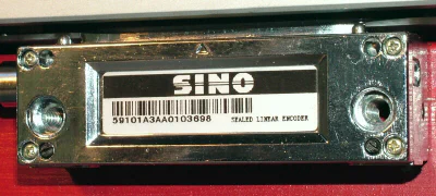 Sensor unit - adjusting screws are the black setscrews
 Final installation with chip shield in place
Control Console Installation
The last task is to mount and connect the digital control console. This could have been done earlier in the process, or even as the first step, and in fact, I did a partial installation of the console about mid-way through the project to get a better feel for how the cables would run to it.
In choosing a location for the display console, I decided that it would need to go on the left side of the mill to avoid having it in the way of the 3-spoke handwheel on the right side.
Because I’m right-handed I thought at first that it might be more convenient to have the console mounted on the right side of the column, but I soon realized that for many operations I stand to the left side of the mill to keep a hand on the power feed lever.
Therefore, the left side mounting of the DRO has worked out well.
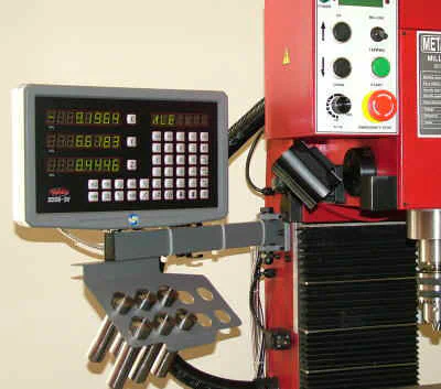 Console mounted on left side of column
I tried to choose a height that would be comfortable when extending my arm out to change settings on the console. It turned out that my first attempt was a little too low, since I had forgotten to take into account a swing-arm adjustable lamp that I had mounted near the back of the mill bench.
I had removed the lamp while I was working on setting up the X-axis. When I put the lamp back in place, I discovered that it was too tall to swing under the support arm of the control console.
This was easily fixed by raising the mounting location of the console by about two inches.
A swing-arm support is provided and it’s a pretty straightforward operation to mount it to the side of the mill column. I chose a height that would be comfortable to reach for operating the console buttons and also to minimize interference with the heavy armored cable that runs between the column and the head.
Also, I needed to mount it far enough back to be clear of the large cam that operates the Z-axis limit switches. Set screws near each corner of the bracket can be used to compensate for shallow angles or irregularities in the casting of the mounting surface.
On the SX4, the column is flat and vertical so the screws weren’t needed.
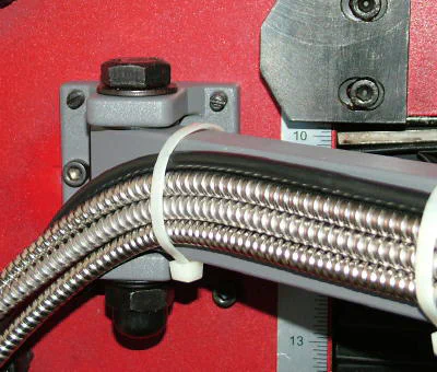 A sturdy bracket mounts the support arm to the column
A bracket assembly secures the console to the support arm and allows the console to be tilted to a convenient angle vertically from about 15 forward to about 45 backwards and also to rotate horizontally through about a 90 arc.
A collet rack with holes for eight R8 collets mounts just below the console providing convenient access to your most frequently used collets.
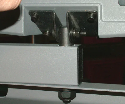 Bracket allows the console to tilt and swivel
Once the console is mounted, the next task is to connect the cables to the back and secure them to the support arm and beyond. The plugs are standard DB-9 and are secured using the screws built-in to the plug housing.
A set of extruded aluminum brackets is provided for securing the cables to the console support arm, but I decided just to use cable ties. Some are provided with the DRO, but I used some longer and heavier ones that I had on hand.
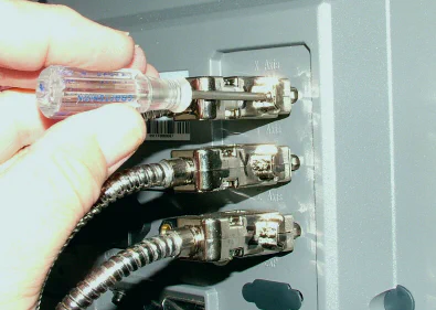 Securing the cables to the console
The final task to complete the installation is to do some “cable control” - i.e. secure the extra length of the cables so that they don’t get in the way during operations.
To accommodate any style of mill or other machine for which the DRO may be purchased, the cables provided are 5 feet long - plenty long for a mill of this size - so you actually end up with extra cable that needs to be collected in a neat loop and mounted near the back of the mill where it will be out of the way.
I also used another of my shop-made cable guides to route the X- and Y-axis cables to the back side of the mill where they are gathered in a loop and secured.
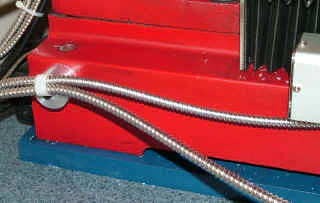 Shop-made cable guide for X- and Y-axis cables
Operating the DRO Console
The console displays the current X-, Y- and Z- coordinates in bright green LED numerals about .6" high. They LEDs have good contrast and, even with my aging eyes, I can easily read them from 6 feet away; at least with my glasses on.
They actually look sharper than in the photograph - digital cameras often have trouble accurately rendering digital displays.
The number of digits after the decimal can be set to 6 or 4; I decided that 4 (ten thousandths of an inch) was enough for my needs. Each axis can independently be zeroed by pressing the X, Y or Z button and then pressing the CLS button.
The membrane buttons give a tactile click when pressed and are integral to the display panel to help seal out any shop fluids that might get on the display.
For extra protection, a clear, flexible plastic cover is included.
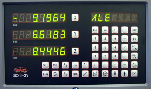 Console display and control buttons
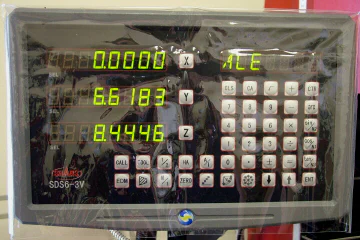 Console with protective cover in place
Another LED display shows the current operating mode and information related to programming automated operations. While I purchased the DRO just to provide accurate readouts of the axes, the internal computer of this unit provides for programming common operations such as laying out a bolt circle.
Once the size of the circle and the number of holes is entered, the DRO will guide you precisely to the center of each hole. I haven’t had time (or need) to play around with these automated functions, so I won’t cover their operation here - maybe in a follow-up article at a later time.
Summary
Although I have not yet used it enough to tap into more than just the basic features, I already find this DRO to be indispensible. The display is steady and bright and, on the Super X4 at least, it’s no problem to set the table to a location accurate to a ten-thousandth of an inch.
The swing-arm and tilt features of the console make it easy to adjust to a comfortable operating position. All said, it’s doing exactly what I hoped it would do.
The manufacturer has done a great job of providing a large collection of bolts, washers, shims and brackets to accomodate just about any conceivable installation.
Of course, as I did, there’s no reason not to come up with your own mounting solutions where it’s expedient, so long as you adhere to the guidelines in the installation manual.
Two separate manuals are provided - one detailing the installation process and the other for operating the features of the console. While they sometimes run into the obscure translations often found in the manuals for imported tools, for the most part, the manuals are understandable, well written and nicely illustrated, as shown in the sample below.
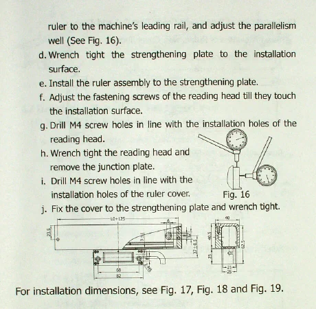
There were a few terms or descriptions that were not at first clear to me, but after re-reading them and studying the diagrams, I was able to move forward and make good progress through the installation.
In conclusion, I can certainly recommend this DRO setup to others. Depending on your machine, you may of course need a different configuration and Shars Tool has several packages in varying dimensions to choose from.
My experience with Shars was very good - they communicated quickly and clearly by email when I had questions and shipped my order in record time. They assured me that I could call for help if I needed it.
At just over $700 ($710 as of 09/10), this DRO kit is a significant investment for the hobbyist or small shop.
However, if you’ve already made the decision to invest in a substantial mill such as the Sieg Super X4, it makes sense to have a quality DRO that can let you use the machine’s full potential. And your time is valuable: getting measurements right the first time is critical.
From that perspective, I feel that the price is reasonable and that this is a good investment. I’m confident that if some years down the road I decide to sell the Super X4, I’ll get back a good percentage of what I’ve invested in it, including the DRO.