Mini Mill Introduction
After I became accustomed to having the mini lathe at my disposal, I soon recognized an insatiable need for a milling machine.
You can make many things on a lathe, but the lathe is very limited when it comes to working with pieces that are not basically cylindrical in shape. A mill is needed to make all the other parts that can’t be made on the lathe. Here are some examples:
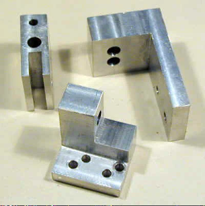
I purchased the Grizzly mini-mill (G8689) in January, 2000, not long after it first was offered by Grizzly.
I have used it extensively since then and have been very satisfied for the most part. See the Features page for a detailed description of this mill.
The mill sells for $495 plus $55 shipping, for a total of $550 as of 03/02. During the summer and holiday seasons it has gone on sale for about $20 less.
If you are an experienced machinist, accustomed to Bridgeport and similar mills, you may regard this tool as a toy.
But for the amateur and hobbyist who can take the time to improve it and work around some of its limitations it provides a fairly low-cost way to own a mill and opens up a tremendous new range of capabilities.
Adapting a Drill Press or Lathe as a Mill
On the 7x10 interest group, the question of adapting a drill press for milling comes up frequently. The conclusion invariably reached is this: you can do it but it’s not worth the trouble.
You will end up spending a lot of time and a fair amount of money, only to end up with a very poor substitute for a mill. Additionally, it will probably be unsafe in operation.
I tried it myself, and I don’t recommend it. A drill press is simply not rigid enough for milling and is not designed to handle the sideward forces imposed on the spindle.
Now, you can, of course, do some limited milling operations on the lathe by making a milling adapter, but, while safe and practical, this arrangement is no substitute for a dedicated milling machine.
The mill provides a much greater range of movement in 3-axes. Having a separate mill also means you can switch quickly from lathe operations to milling operations without having to reconfigure the machine each time.
This may be a worthwhile project for you, though, if your milling needs are very limited or while you are saving up money to buy a real milling machine.
How a Milling Machine Works
For those of you who may not be familiar with the operation of a milling machine here’s a quick rundown. First, a note on terminology.
A milling machine is often referred to simply as a ‘mill’; however, the cutting tools used in the milling machine are sometimes also referred to as ‘mills’.
There are two main varieties of milling machines: vertical and horizontal. The Grizzly mini-mill is a vertical mill, in which the axis of the spindle is vertical. Horizontal mills have a horizontally oriented spindle and use a different type of cutting tools.
We will not discuss them here, but if you would like more information, see the U.S. Army machine tools manual.
The spindle is the main rotating shaft in which the cutting tools are mounted. In essence, a vertical mill is much like a very robust drill press supplemented by a work table which can be moved side-to-side and front-to-back very accurately.
Here’s a stylized diagram showing the main components of a vertical mill in a side-view:
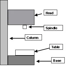
In operation, the workpiece is securely clamped to the table or is held in a vise clamped to the table. The milling tool rotates, much like a drill bit, and the work is advanced past the cutting tool by means of the hand wheels that move the table.
As cutting progresses, the head can be lowered in accurate increments of a few thousandths of an inch until the desired depth of cut is achieved.
End Mills
The most common cutting tool used with a vertical mill is an end-mill, which looks like a stubby twist drill with a flattened end instead of a point.
The following photo shows several varieties of end mills. Visit the End Mill page for more information.
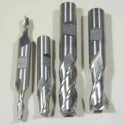
An end mill can cut into a workpiece either vertically, like a drill, or horizontally using the side of the end mill to do the cutting. This horizontal cutting operation imposes heavy lateral forces on the tool and the mill, so both must be rigidly constructed.
By making a series of horizontal cuts across the surface of a workpiece, the end mill removes layers of metal at a depth than can be accurately controlled to about one one-thousandth of an inch (.001").
Head and Spindle
The mill spindle is mounted in precision bearings in the head casting. A collet or end-mill adaptor mates with the tapered socket of the spindle and holds the end-mill tightly in place and accurately centered on the spindle axis.
The entire head assembly can be moved up and down along a column. On the mini-mill, both a coarse and fine movement control are provided.
When the head is at the desired position it is locked in place before beginning the cutting operation.
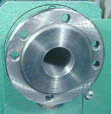
Table and Handwheels
Mounted below and precisely perpendicular to the spindle is the mill table. The top surface of the table is ground to form a flat and even surface and is slotted so that mounting bolts can be inserted to clamp work to the table surface.
Often a milling vise is mounted on the table by means of clamps and the workpiece is clamped in the vise. In any case, the workpiece must be rigidly attached to the table.
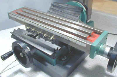
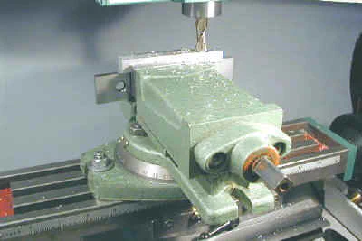
The table can be moved both front-to-back and left/right relative to the base of the mill. This movement is controlled by leadscrews with hand wheels and can be controlled to a precision of about .
001" in either axis. Calibrated collars on each leadscrew enable the operator to move the table a specified distance in either direction.
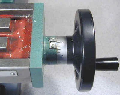
The left/right movement is referred to as the ‘X-axis’, the front/back movement as the ‘Y-axis’ and the up/down movement of the spindle as the ‘Z-axis’.
Milling Operations
Typically, before milling, a workpiece is painted with a special marking dye and then scribed using precise measuring tools to provide guidelines for the milling operation.
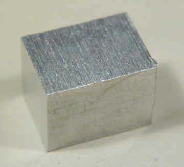
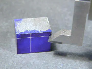
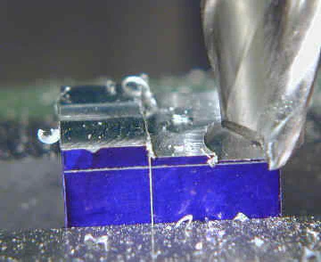
Next, the workpiece is clamped in the milling vise, or directly to the table. An end mill of the appropriate diameter is mounted in the spindle and lowered until the tip is nearly contacting the top surface of the work.
Then, the mill is powered on and the cutting tool is lowered until it will remove a known amount of material (usually .001 to about .030) per pass.
Using the X and Y-axis hand cranks the work is advanced past the rotating end mill to remove a layer of material. This process is repeated as many times as necessary to cut the workpiece to the desired shape and dimensions.
The mini-mill also serves as a precision drill press. It comes with a large chuck which can hold twist drills up to 1/2" in diameter.
The precision results from the ability to accurately position the hole by means of the X and Y axis hand wheels.
The depth of the hole can also be exactingly determined by means of the Z axis control.
Don’t throw away your drill press, though. While precise, the mini-mill lacks the throat depth and vertical range of most stand-alone drill presses.
Plus there will be times when you have a complex workpiece set up in the mill, but need to drill a quick hole in some other piece.