Making Handwheels
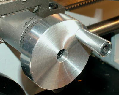
If you do a lot of work on the mini-lathe, you may find, as I do, that the stock handles for operating the cross-slide and compound are not optimal. I have beefy fingers and they sometimes can get pinched between the stock handles.
My knuckles get beaten up by the protruding hex cap screw that holds the handle in place. The roller handwheel described below solves these problems and makes it quicker, easier and smoother to move the cross-slide in and out.
The roller handle is used to move the cross-slide rapidly, as, for example, when you need to back it out to do a drilling operation using the tailstock.
For fine control, the handwheel is grasped along the outer edge and slowly turned. Using a two-handed technique, you can keep the cross-slide moving at a relatively even pace to get a fine finish on a facing operation.

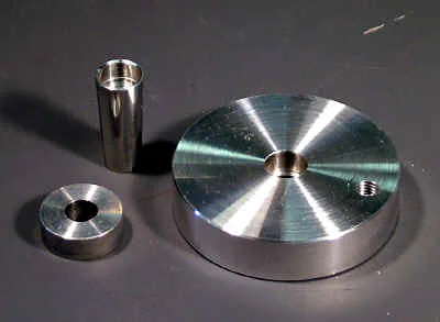
The cross-slide roller handwheel has four components:
- Disk
- Spacer
- Tapered roller handle
- 1/4"-20 x 1-1/2" socket head cap screw

Note: the shaft of the cross-slide is 8.0mm (0.3150") so the through hole ideally should be drilled with an 8mm drill. A 5/16" drill is very close (0.3125") and may work but may require drilling out with the next larger size 21/64 (0.3281"). Try this on a test piece before machining the handwheel. A letter ‘O’ drill is even better (0.3160") if you have one.
Dimensions: 2.250" x .525" (both dimensions ± .050")
Material: 2-1/4" aluminum rod
-
Cut stock to a convenient working length (~2")
-
Mount in 3-jaw chuck
-
Face the end
-
Center drill
-
Drill through 8mm (*5/16") dia.
-
Counter bore to depth of .220" ± .020". Be careful not to drill all the way through.
-
Counter bore with 5/16" end-mill to flatten the cone of the drilled hole
-
Turn outside surface to a length of ~ 3/4", just deep enough to get a clean surface
-
Chamfer front edge using a file or cutting tool to remove sharp edge
-
Remove stock from lathe;
-
Cut off to length of ~3/4" (just past finished area) using hacksaw or bandsaw
-
Insert 5/16" x 1" (or longer) bolt through center hole with head on finished side of workpiece
-
Secure bolt with nut and firmly tighten
-
Remount workpiece in chuck grasping head of bolt; so that unfinished side is towards tailstock
-
Face to a finished thickness of 0.525" ± 0.050"
-
This completes the lathe work on the cross-slide handwheel
-
Mount workpiece in drill press vise
-
Use a Sharpie pen or center punch to mark a point ~.250" from edge of front (counterbored) side
-
Mount workpiece in drill press or milling vise; use parallels or a block underneath so that it is level
-
Center drill a starter hole at mark
-
Drill through with #7 drill (Or, if you want to keep the back side of disk smooth, drill to a depth of about 0.010 less than the thickness of workpiece; but it’s easier to tap if you drill all the way through)
-
Tap 1/4-20
-
Clean chips from tapped hole using a small amount of tapping fluid
-
Remove workpiece from vise and clean up with soap and water
-
This completes the cross-slide handwheel
Spacer (goes between handwheel and calibrated dial)
Dimensions: Diameter can be anywhere from .5" to 1". Thickness 0.280 ± .010"
Material: Aluminum rod
- Mount a length ~2-3" of stock in 3-jaw chuck
- Face the end
- Drill 8mm (or *5/16") to a depth of about 1/2"
- Cut off end of workpiece to a length of about 1/2". (Use a cutoff tool on the lathe, or remove from lathe and cut off with hacksaw or bandsaw)
- Insert 5/16" x 1" (or longer) bolt through center hole with head on finished side of workpiece
- Secure bolt with nut and firmly tighten
- Remount workpiece in chuck grasping head of bolt; so that unfinished side is towards tailstock
- Face to a finished thickness of 0.280" ± 0.010"
- This completes the lathe work on the spacer
Tapered Handle
Mounts in tapped hole using 1/4"-20 x 1-1/2" socket head cap screw. (On mine, I used a 6mm-1.0 x 30mm bolt which is similar in size.)
Dimensions: Length: 1.125" ± .010"; Diameter tapers from about .485 to about .385.
Material: 1/2" diameter aluminum rod
- Mount a length ~2-3" of stock in 3-jaw chuck
- Face the end
- Drill 1/4" to a depth of about 1-1/4 - 1-1/2"
- Counterbore with 3/8" dia. end-mill to a depth of .200 ± 0.020" (provides a flat face for the head of the cap screw; could be drilled with 3/8" drill, but that would leave a conical face, so the end-mill is preferred.)
- Adjust compound to 4 on right side of protractor (cutting inwards)
- Mount cutting tool so that tip is approximately perpendicular to the cut; square toolpost aligned with compound
- Starting at the right end, take a series of cuts until the taper extends to a length of about 1.250". Take several light finishing cuts while nearing the final length.
- Polish the tapered part with Scotch-Brite pad, emery cloth or 400-grit wet-dry sandpaper to remove tool marks
- Cut off tapered part to a length of about 1-1/2"; use a cutoff tool, or remove from chuck and use a hacksaw
- Insert 1/4 x 2" (or longer) bolt through center hole with head on counterbored side of workpiece
- Secure bolt with nut and firmly tighten
- Remount workpiece in chuck grasping the nut; so that unfinished side is towards tailstock
- Face to a finished length of 1.125" ± .010"
- This completes the lathe work on the tapered handle
Assembly
- Lubricate the cap head screw from the head end of the thread down to about 3/8" from the tip with light grease
- Place the screw through the roller handle with the tip of the screw at the narrow end of the handle
- Put a few drops of LocTite or superglue on the last 1/4" of the tip of the thread
- Screw the handle and bolt into the threaded hole in the disk until the tip of the narrow end of the handle nearly touches (but not quite) the face of the disk. There should be just enough clearance so that the roller handle turns freely.
- Allow about 10 minutes for the glue/LocTite to set. Rotate the handle periodically to prevent it from getting glued in position if any glue got on it.
- Slide the spacer onto the cross-slide shaft
- Slide the roller handle disk onto the cross-slide shaft
- Use the original cross-head screw to secure the roller handle disk on the shaft.
- This completes the assembly. The handle is now ready for use.
 Spacer installed