Homier 7x12
If you are a regular reader of mini-lathe.com or the 7x10 Interest Group, you know that in the summer of 2001 Homier introduced a new version of the 7x12 mini-lathe at the remarkable price of $299 and with some unique features not found on the mini-lathes offered by the other vendors.
Many customers snapped up these new lathes and found them to be a great bargain. Here’s a link to the review of the older version and a comparison of the old and new versions.
By Fall of 2002, reports started emerging that Homier was shipping a slightly different version of the lathe, missing some of the unique features we had come to associate with the Homier model, but still at the compelling $299 price for a 7x12 lathe.
Further research verified that these new model lathes are made by Sieg, the same manufacturer who makes the mini-lathes sold by the other vendors. This review will provide you with an up-close and personal assessment of the new model.
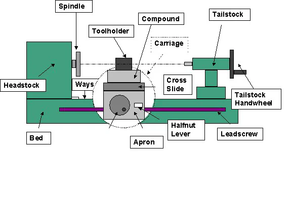
If you are unfamiliar with lathes and their terminology, refer to the Introduction Page and Glossary. The following diagram should help:
Receiving and Unpacking
The lathe arrived by UPS and was left on the front porch of my house. This is common practice in my neighborhood and over many years of deliveries I have never had any problems.
However, the contents of the box are clearly marked on the outside, including some nice photos of the lathe, so you may want to request that someone be present to receive the lathe if you have one shipped to a less tranquil neighborhood.
At around 90 lbs., though, it’s not too likely that someone will pick this up and run off with it.
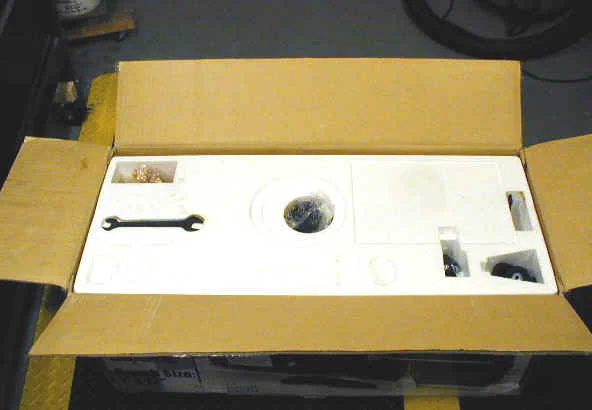
The cardboard shipping carton has been reinforced by particle board panels held in place by steel strapping. Two bolts pass through the bottom panel into the bed of the lathe.
The bolts on mine were pretty well bent up, but inside the styrofoam inner packing I found the lathe to be in perfect condition. This is a big improvement over the prior version of the Homier lathe as well as earlier versions of the Sieg lathe shipped by other vendors in which minor damage, especially to the chip tray, was almost a certainty.
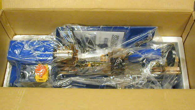
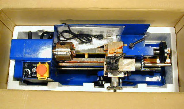
Note that the cross-slide handle is mounted in reverse, with the handle pointing inwards, to protect it from damage. Remove the hex nut that holds it in place, then remount it with the handle pointing outwards.
You may need to pry it gently off the shaft using a pair of flat-blade screwdrivers.
The lathe is an attractive royal blue color - just like the old version. Before you can remove the lathe from the box, you must remove the holddown bolts from the bottom of the box.
This is somewhat problematic as you will need to set the box on some kind of supports that allow you to access the bolts. Expect the bolts to be bent and require some effort to remove.
Once they are out of the way, you can lift the lathe from the box. This is best done with the aid of a helper. Be careful when grasping the headstock (left) end of the lathe not to use the gear cover as a handhold or it may break under the weight of the lathe.
Accessories
All of the accessories were tucked into recesses in the styrofoam packing to keep them from banging around in the box and causing damage. Those such as the dead center which have any risk of rusting were packed in red packing grease inside of plastic bags.
Fortunately, most (but not all) of the tools you need to set up and maintain the lathe are included as accessories.
Included Accessories:
- Oil Bottle
- Rubber Feet and mounting bolts (4)
- Handles for carriage and tailstock handwheels (2)
- Dead Center for tailstock
- Open end wrenches (metric) (2)
- Change gears for thread cutting (9)
- Chuck key
- Hex wrenches (metric) (4)
- Outside jaws for chuck (3)
Compared with those provided by Sieg in previous years, the manual has been rewritten in much better English and with more complete descriptive information. Setup and safety concerns are covered, as are basic lathe operations.
However, if you are not already experienced and familiar with lathe operations you will find the descriptions in the manual to be insufficient. You can find additional helpful information on the mini-lathe.com Operations and Tool Grinding pages.
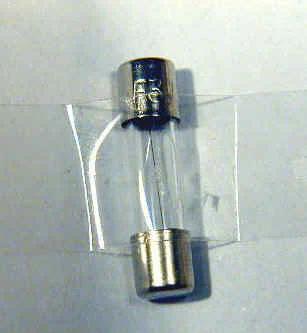
Be careful not to throw out the spare fuse, which is taped to a little piece of paper in the plastic bag containing the manual.
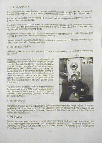
The main tools you will need that are not provided are a 1mm hex wrench and 7mm open end wrench for adjusting the gibs.
I highly recommend that you purchase a set of T-handle metric hex wrenches to have on hand when the lathe arrives as you will find them quite handy every time you use the lathe. Here are some other things that are good to have on hand:
- 5/16 Tool Blanks
- Bench grinder for shaping tools
- 7mm open-end wrench and 1mm hex wrench to adjust gibs
- T-Handle hex-wrench set
- Dial caliper
- Safety glasses (I use heavy plastic reading glasses)
- Round Stock: aluminum, brass, steel in various diameters
- Drill chuck and arbor for tailstock
- Center drills
- Live center (comes with Harbor Freight 7x10, but not Grizzly 7x12 or Homier 7x12)
- Inch and number drill sets
- Assortment of taps 4-40, 6-32, 8-32, 10-32, 1/4-20, 3/8-16 etc.
Many other accessories are available for the mini-lathe. A particularly important one that is not included is a tailstock drill chuck and mounting arbor.
You can obtain these from Micro-Mark, Harbor Freight, LittleMachineShop.com, Grizzly and other sources. The arbor tang must be cut down to fit properly in the tailstock bore. A Dremel cutoff tool does the rough work, followed by cleanup on the grinder or disk sander.
Bed and Ways
A sturdy cast iron bed forms the foundation on which the lathe is constructed. It is quite rigid and heavy enough to keep the lathe anchored to the workbench.
Four rubber feet are provided and screw into threaded holes on the underside of the bed casting. They will help to keep the lathe from moving around during relatively light work, but for heavier work, bolting the lathe to the workbench top will provide much better results.
A drilling template is provided in the manual to facilitate this procedure. A sheet metal chip shield extends about 2/3 of the length of the bed. It is useful for catching chips that would otherwise end up in areas that are difficult to clean up, and also limits cutting fluid and oil or grease from the chuck from spraying around.
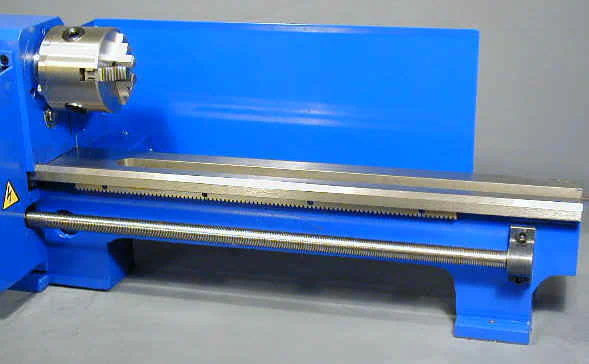
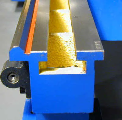
The ways are the precision ground surfaces on the top of the bed along which the carriage travels. The front way has an inverted V shape that acts as a guide for the saddle, while the rear way is flat.
They are nicely finished, but not hardened as you would expect to find on an expensive industrial lathe. As long as you take care not to drop the chuck or heavy tools on the ways they will provide many years of service.
Headstock and Spindle
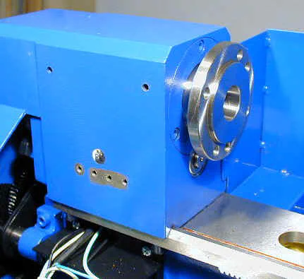
Looking from the front of the lathe, the headstock is a casting on the left end of the bed that encloses the speed-change gears, the spindle and the spindle bearings.
On the mini-lathe, the headstock is mostly hidden behind the electronic speed control housing. In the following photo, I have removed the control housing to provide a better look at the headstock casting.
Look carefully and you can see that the lower front edge of the headstock casting has a V-groove that mates with the V of the ways to ensure proper alignment of the headstock and spindle with the ways.
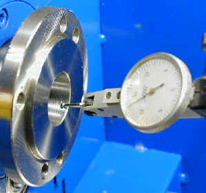
Ultimately, a lathe can be no more accurate than the spindle runout, or side-to-side play, as any movement of the spindle within its supporting bearings will translate directly to movement of the workpiece. On an inexpensive lathe such as this, a runout of .001" at the spindle would be acceptable.
Fortunately, most owners of the 7x lathes report runouts of less that 0.0005", which is surprisingly good for such a low-priced tool. On this lathe, the runout as measured on the surface of the Morse taper is .0003". Measuring along the rim of the raised boss the runout was 0.0001 or less.
Motion of the indicator needle was just barely perceptible. This may be because the boss was actually turned to final diameter after the spindle was mounted in the lathe.
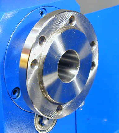
The spindle plate has a raised area that mates with the back of the chuck to ensure proper alignment of the chuck. Six mounting holes are provided to allow direct mounting of the standard 3-inch 3-jaw chuck or an optional 3-inch 4-jaw chuck. For more information on optional chucks, see the Chucks Page.
Below the spindle you can see the drive shaft and bearing for the HI / LO gear assembly. The motor turns this shaft by means of a toothed belt and the gears inside the headstock drive the spindle.
This is another nice feature of the mini-lathe, as the power is applied between the spindle supporting bearings rather than to the left end as is found on many inexpensive lathes.
An important dimension of any lathe is the diameter of the spindle hole as this determines the largest diameter of stock that can pass through the spindle.
This, of course, lets you chuck a length of stock so that you can work with the right end protruding a small amount from the chuck for rigid support, while the remaining length of the stock extends out through the spindle to the left.
This lathe sports a #3 Morse Taper spindle with a through hole of 5/8", which is larger than you might expect for a small lathe. In fact, it is the same size you will find on the larger 9x20 class lathes.
Varmint Al was the first to determine that you can safely ream the hole out to 13/16", allowing a piece of 5/8" stock to fit through the spindle, and many owners, myself included, have done this.
Varmint Al generously loaned out his reamer by mail to anyone who wanted to use it, provided they shipped it to the next person on the list. Although some unscrupulous individual ripped off Al’s original reamer, this practice continues with one or more replacements.
to get on the distribution list. Incidentally, LittleMachineShop.com is an excellent source for replacement parts and accessories for the mini-lathe.
On the back side of the headstock are two levers: the HI / LO range lever and the leadscrew directional control lever. The HI / LO lever shifts a set of gears internal to the headstock.
The great majority of work on the lathe is done in LO range with a maximum of about 1250 RPM. HI range is used primarily for polishing and similar operations with a maxim RPM of about 2500 RPM.
In HI range, of course, the available torque is about half that in LO range. The function of the leadscrew directional lever is explained below.
Electronics and Motor
One of the nicest features of this lathe is the electronic speed control. Unlike most lathes that use a belt and step-pulley arrangement to change speeds, this lathe provides continuously variable speeds simply by turning a control knob.
You can even adjust the speed while the lathe is turning if you sense that it needs to be a little faster or slower for the operation you are performing.
Removing the control housing (unplug the lathe if you do this!) reveals the speed control board and controls. The circuit board is covered by a piece of clear plastic that helps to keep metal chips from shorting out the electronics.
Some owners have improved the odds by sealing around the edges with tape or silicon sealant. The speed control is pretty sophisticated as it dynamically adjusts the torque of the motor as the load is increased.
It provides substantial torque even at the minimum RPM setting of about 40 RPM.
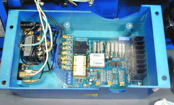
Mounted on the front of the headstock casting, the electronics control housing encloses the speed control circuit board and serves as a console for the controls.
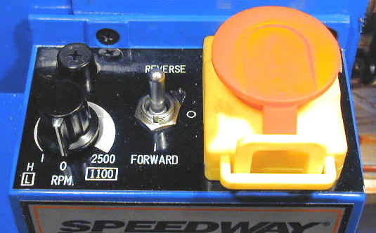
The controls are as follows:
- Fuse holder (top left)
- Speed control knob (lower left)
- Forward / Neutral / Reverse toggle switch (center)
- Power switch and emergency cutoff (right)
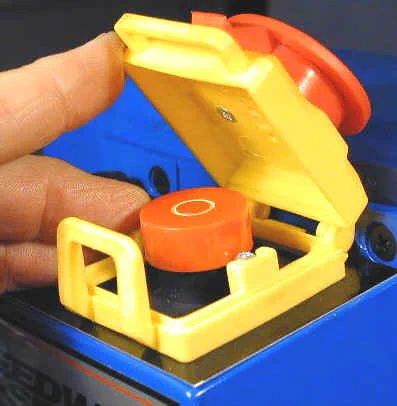
The BIG RED BUTTON actually is really just a plastic cap that covers the LITTLE RED BUTTON. The red cap slides forward under spring pressure to engage with the yellow tab so that the button underneath is held in the depressed position.
In this position the power to the lathe is cut off. A small luggage-type padlock can be looped through the yellow tabs as a child-safety lock. When the lathe is in use, the red plastic button is disengaged from the yellow tab exposing the button underneath and allowing it to pop up which applies power to the lathe.
In an emergency, you can mash your hand down on the red plastic cap to cut off power to the lathe.
Any time the lathe is stopped by the toggle switch or the power switch, the speed control knob must be reset to zero before the lathe will run again. This is a safety feature that prevents the lathe from unexpectedly starting up at high speed when one of the switches is engaged or in the event of a power failure.
The dark side of the electronic speed control is that it has proven over the last few years to be the single most common failure point on the 7x mini-lathes. Typically, when it fails, it is due to the power MOSFETS getting fried with the result that the motor will run only at full speed.
Fortunately, all of the vendors have honored the warranty and replace the power supply board at no cost if it is within the warranty period. After that, you are on your own, but replacement MOSFETS can be purchased for about $10 per pair from LittleMachineShop.com.
It is evident that the engineers at Sieg have significantly improved the design of the speed control circuit board over the last few years and the version in this lathe uses a single board with surface mount technology.
Hopefully, this improved design will prove to be more robust. To improve the odds, here are some tips:
-
When stopping the lathe between operations, turn the speed control knob counterclockwise until it clicks off; don’t use the toggle switch or red power switch for this purpose.
-
After stopping the lathe with the speed control knob, use the silver toggle switch to reverse the direction, if necessary.
-
Use the red power switch only after turning the speed to zero, and only when you are done using the lathe for the current work session.
-
Use the red power switch if necessary as an emergency cut-off, but not for routinely stopping the lathe.
-
Attach a little brush or rubber seal to the opening where the leadscrew enters the speed control housing to keep metal chips out of the electronics.
-
Remove the electronics housing (with the lathe unplugged!) and seal around the edges of the plastic sheet that covers the circuit board with electrician’s tape or silicon sealant.
The motor is mounted on the back side of the lathe below the headstock. The manual designates it as 1/2 HP, but I suspect it is more like 1/3 HP. Either way, it has ample power and torque to handle most jobs within the capacity of the lathe.
When turning or facing work larger than 3" diameter, though, you will find that you must take lighter cuts to keep the motor from bogging down. I would happily trade off more of the upper speed range for more torque in the lower range.
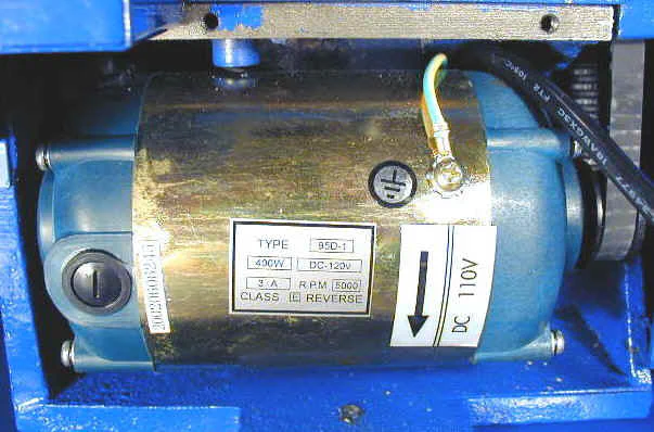
Power from the motor is transferred by means of a toothed belt and pulleys to the drive shaft mounted in the headstock. From there, the HI / LO range gears inside the headstock transfer power to the spindle.
Change Gears
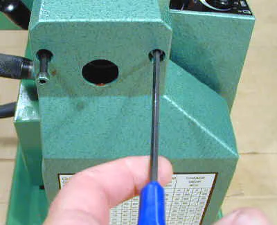
A set of gears provided with the lathe may be interchanged to cut threads in many inch and metric pitches. Use a 4mm hex wrench to remove the two screws retaining the gear cover.
Clean up the gear train using a brush and solvent. A chart of thread pitch settings on the gear cover shows the combination of gears required to cut a specified thread pitch.
The gears are manually removed and installed to set up the proper gear train for thread cutting.
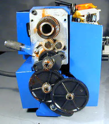
Driven by the gear train, the leadscrew can be set to clockwise or counterclockwise rotation or may be set to neutral so that it does not rotate. These options are set by means of a lever on the back side of the headstock.
A knurled sleeve locks the lever in place. Grip the sleeve tightly and pull back firmly to unlock the lever and you can move it to one of three positions: UP, NEUTRAL and DOWN.
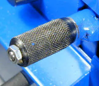
In the UP position, the leadscrew will drive the carriage towards the headstock when the motor is turning in the forward direction. In the DOWN position, the carriage moves away from the headstock.
Since the direction of the motor and the direction of carriage movement can be independently controlled, you can cut both left- and right-hand threads and can cut either towards or away from the headstock with properly formed cutting tools.
This flexibility is one of the features that makes this lathe unique for its size and cost.
Leadscrew and Half Nut
Running along the length of the bed, the leadscrew is a 16 thread-per-inch (TPI) Acme thread that serves to drive the carriage under power for turning or thread cutting operations.
Using the provided set of change gears, you can cut a wide variety of inch threads as well as metric threads. Because the leadscrew is an inch pitch, the metric threads are only approximate, but are close enough for most applications.
You will find detailed instructions on thread cutting on the Premium Content Thread Cutting topic.
Mounted on the apron (the front of the carriage), the half-nut lever engages and disengages the carriage from the leadscrew.
With the motor running in the FORWARD direction, and the leadscrew lever in the UP position, engaging the half-nut lever drives the carriage towards the headstock.
This is the most common setup for performing turning operations under power on relatively long workpieces and for cutting right-hand threads. Moving the leadscrew lever to the DOWN position moves the carriage away from the headstock.
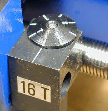
A threading dial is provided to properly synchronize successive cuts when cutting threads. The dial rotates as the leadscrew turns and the markings on the dial show the proper point at which to engage the half-nut.
Details of operation may be found in the Thread Cutting premium content topic.
Carriage
The carriage is the entire moveable assembly that supports the cross-slide, compound and toolpost. It consists of the saddle, an H-shaped casting that rides on the ways, and the apron, the casting bolted to the front of the saddle on which the carriage handwheel and half-nut lever are mounted.
The carriage may be moved manually by means of the carriage handwheel or under power by engaging the leadscrew with the half-nut. The half-nut is a split-nut arrangement that opens or closes around the leadscrew to engage or disengage the carriage power feed.
The carriage handwheel, makes it easy to rapidly crank the carriage to a desire position along the ways, but can also be carefully turned for short cutting operations.
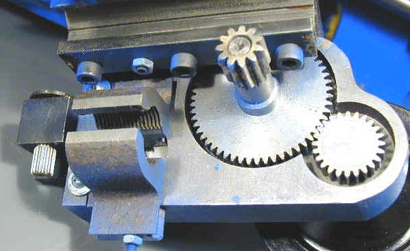
It operates by means of a rack mounted underneath the front of the ways and a pinion gear on the back side of the apron. The following photo shows the back side of the apron, including the half-nut and pinion.
The carriage is held tightly to the ways by means of two metal strips which I refer to as the saddle plates. Some users refer to them as gibs, although, strictly speaking, they are not. But they serve a similar purpose in that they are adjustable to allow the saddle to slide freely along the ways with minimal play.
This adjustment is important since any play between the saddle and ways will be magnified at the tip of the tool, resulting in chatter. Adjusting them is a patience-testing exercise as they are not easily accessible unless the carriage is removed from the ways.
I have developed a modification that solves this problem by making them adjustable from the top of the saddle.
Cross Slide and Compound
In its simplest form, a lathe must provide a way to rotate the work, move the cutting tool back and forth along the length of the work and move the tool in and out across the diameter of the work.
The carriage provides the lengthwise motion and the cross-slide provides the in and out motion. Modern lathes, including this one, often provide a compound slide which can be set at an angle to the lathe axis for cutting champfers, bevels, short tapers and screw threads.
The cross-slide is mounted on top of the carriage and the compound slide, often just referred to as the compound, rides on top of the cross-slide.
Mounted on top of the carriage, the cross-slide moves the cutting tool in and out perpendicular to the lathe axis to control the depth of cut. As described in the next section, calibrated dials facilitate taking cuts turn a workpiece to a specified diameter.
Dovetail grooves on either side of the slide provide a sturdy platform that remains aligned as it moves. The cross-slide is driven by a metric leadscrew with a 1mm pitch. The leadscrew engages with a bronze nut that can be canted slightly to compensate for backlash.
Three screws on top of the slide are used to make this adjustment.
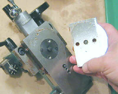
On the side of the cross-slide and compound you will find a row of three set screws with lock nuts. These are used to adjust the tightness of the gib strips. Gib strips are strips of metal with a diamond-shaped cross section that align with the dovetail slide to make it adjustable.
When the gibs are properly adjusted, the slides will move freely with very little play. The gibs need to be adjusted periodically as the lathe is broken in.
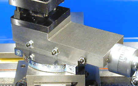
Mounted to the top of the cross-slide, the compound can be rotated and locked in position at an angle relative to the centerline of the lathe. By advancing the compound slide, and thus the cutting tool, along this angle, you can cut short tapers and bevels.
Rotating the compound also provides some flexibility in positioning the tool when cutting larger diameter stock. A calibrated metal protractor aids in setting the desired angle.
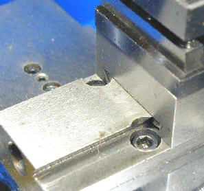
To change the angle of the compound you must crank the slide back until the hidden screws underneath the slide are accessible.
Dials and Handles
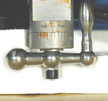
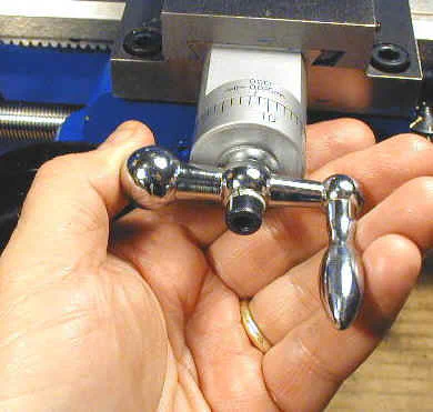
Both the cross-slide and compound have calibrated handwheels with a nice satin finish and high-contrast markings. The handwheels are chrome-plated steel consisting of a shaft with a handle on one end and a ball on the other.
The handle is used to rapidly crank the handwheel for coarse positioning, while the ball may be grasped together with the small ball on the other end of the shaft for fine positioning.
If your fingers are at all beefy, as mine are, you are likely to soon discover an annoying feature that Varmint Al calls the “knuckle buster”. This occurs when your finger gets wedged in between the handle and the cap screw that holds the handle in place.
It is really more of an annoyance than a danger, and I temporarily solved the problem by pressing a rubber grommet over the end of the cap screw. On my working lathe, I replaced the factory handles with roller handles made on the lathe and have never regretted the change.
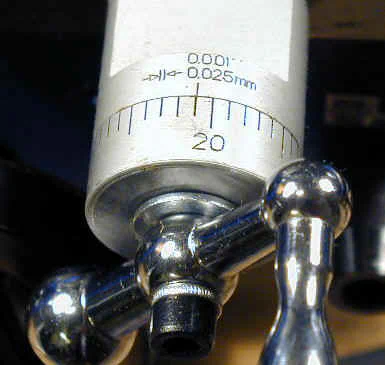
The calibrated dial can be rotated independently of the handle to facilitate setting of a zero reading. Although the markings are increments of .001", the leadscrew thread is actually 1mm metric pitch.
Therefore each full rotation of the handwheel is actually 0.0397" rather than 0.040" as marked on the dials. This small difference is negligible in practical work as long as you don’t count of ten turns of the dial and expect it to move the cross-slide by exactly .400".
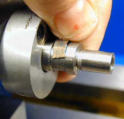
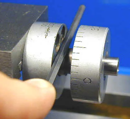
The dials are held in place by friction from a small half-moon shaped spring that sits in a groove between the leadscrew shaft and the calibrated dial.
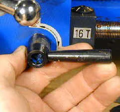
If you remove the dial for cleanup, be careful not to lose the spring and be sure to note the positions of the two washers. When replacing the dial, use a screwdriver or, as shown here, a hex wrench, to depress the spring into the groove as you slide the dial into place.
3-Inch 3-Jaw Chuck
The stock chuck is standard on all the Sieg-made lathes and from my experience with those lathes, I can attest that this is a fine chuck and should do just about anything you would expect from a little chuck on an inexpensive lathe.
It is not unusual for the moving parts to be somewhat stiff until it gets worn in, and this chuck was no exception. It comes with both inside and outside jaws; the outside jaws providing capacity to hold somewhat larger diameters of stock.
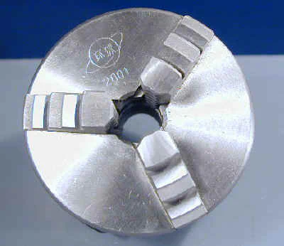
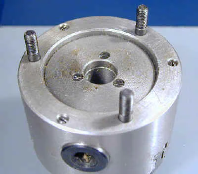
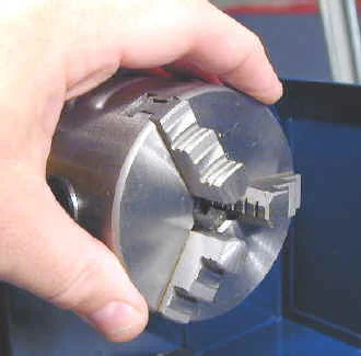
The bottom left hand photo above should give you a good idea of the true size of the chuck. Its small, but you can supplement it with a variety of optional chucks if you need more capacity.
Tools and Toolpost
Mounted on top of the compound, the toolpost is of a 4-sided design capable of holding four different tools at once. The idea here is that you can mount several tools in the holder and index them into working position by loosing the locking nut lever and rotating the toolpost to bring the desired tool into position.
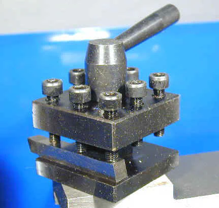
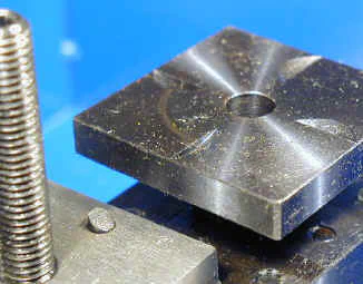
Underneath the toolpost is a spring-loaded detent that engages with notches on the bottom of the toolpost. While intriguing, most users seem to find this feature of little practical value.
In real life, you find that the optimal angle for the tool is not at a right angle to the work, which is where the detent wants it to go. So most of us remove the little spring and detent so we can set the toolpost wherever we need it.
You will also find that if you mount more than two tools in the toolholder at once, the extra tools stick out like little instruments of torture, waiting to impale the unsuspecting hand or arm.
A toolpost that could be adjusted for height would much more useful. The most convenient size tool to use in the stock toolpost is 5/16". The top of such a tool blank will be just above the centerline. As you grind the tool you can trim down the top edge to get it right on center. Unfortunately, this is harder to do than it is to say and, in any case, as the tool is resharpened it ends up below the centerline and must be shimmed.
The height of the tool is very important: just a few thousandths of an inch above or below the centerline will dramatically affect the quality of your work. For that reason, many mini-lathe owners purchase or make an adjustable toolpost to replace the stock one.
A very nice quick change tool post (QCTP) is available from TS Engineering.
Mert Baker, professor emeritus of the 7x interest group, makes and sells a nice adjustable height toolpost that many mini-lathe owners have adopted. It currently sells for $60 including shipping in the 48 states. to order one.
Tailstock
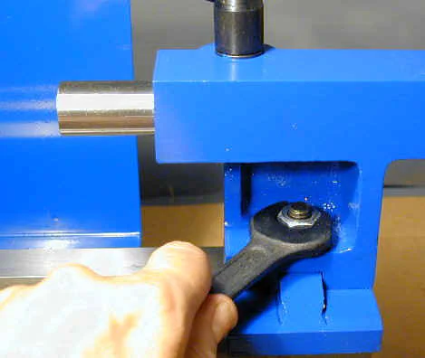
The tailstock slides along the ways and is moved by hand to the desired position and then locked into place by means of a 17mm wrench and lock nut. Although this arrangement gets the job done, it is not a very convenient arrangement because the lock nut may be obstructed by the compound, making it difficult to get at.
That being said, it’s not too difficult to convert the tailstock to a cam-locking arrangement. Trust me, this is one of the best mods you can make to the lathe and the time you spend doing it is well repaid by time saved every time you use the tailstock.
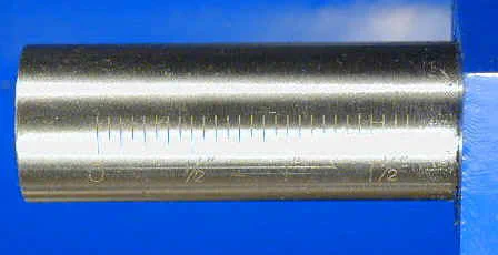
The tailstock ram is advanced and withdrawn by the tailstock handwheel. The handwheel itself is not calibrated, but each revolution advances the ram by 1/16".
Inch divisions down in increments of 1/16" are provided on the side of the ram, but are fairly difficult to read unless you have very good lighting over your workbench.
Together with counting revolutions of the handwheel, they are helpful in drilling holes to a specified depth.
When using a live or dead center in the tailstock to support the end of a workpiece, you can lock the tailstock ram firmly in place by means of the tailstock locking lever.
Out of the box, mine was locked so tight that I had to tap it with a rubber mallet to loosen it, but once freed up, it functioned perfectly. As with the half-nut lever and toolpost lever, a few drops of Loc-Tite on the threads of the handle will keep the handle from working loose from the hub.
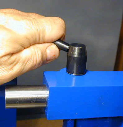
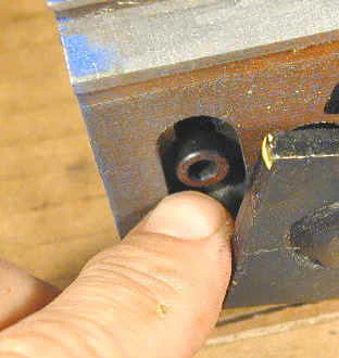
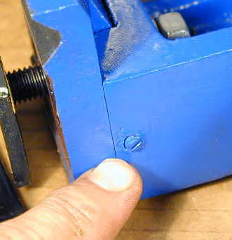
The tailstock has an offset capability that can be used to turn long tapers between centers. Using this feature is somewhat awkward as you must remove the tailstock from the bed and turn it upside down to loosen or tighten the locking screw.
There’s also a set screw on the back side of the tailstock casting that must be loosened. Once both screws are loose, you can slide the upper part of the tailstock side to side over the lower part of the casting to the desired offset and then lock both screws.
Cleaning up the Lathe
Thick red packing grease, typical of all machine tools made by Sieg, protects all of the bare metal surfaces such as the chuck, ways, saddle and compound from rust during shipping and warehousing.
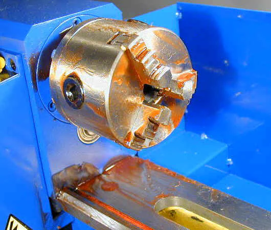
Cleaning off this gunk is one of the rites of passage into the fraternity of mini-lathe owners. Here are some supplies you will need to get this job done efficiently:
- Kerosene or WD-40 - available in 1 gallon cans at Home Depot and similar stores
- Business cards for scraping off thick layers of grease
- Paper towels
- Rags
- A few 1" and 2" ‘chip brushes’ - cheap throw-away brushes with natural bristles
- Newspaper or cardboard to go under the lathe during cleanup process
- Disposable plastic pail for cleaning parts in kerosene
- White lithium grease
Before beginning the cleanup process, its a good idea to attach the handles to the carriage and tailstock handwheels. This will make it easier to move the carriage while cleaning the ways and easier to clean the tailstock ram.
Screw the handle bolt into the handwheel using a flat bladed screwdriver but leave a little room so that the handle can rotate freely on the bolt shaft.
Then tighten the lock nut against the side of the handwheel. Make sure that the half-nut lever is in the UP position so that the carriage is free to move.
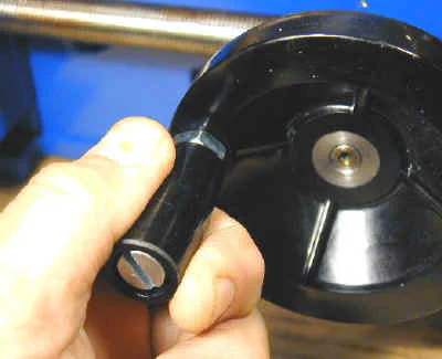
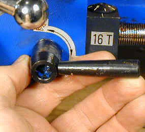
You can clean the lathe on the floor of your workshop but I find it easier to do this operation with the lathe up at bench height (I figured this out after doing 2 lathes and 2 mills at floor level).
I place some heavy corrugated cardboard (conveniently available from the packing box) under the lathe to catch the drips of solvent and dissolved grease.
I begin the cleanup process by scraping off the thickest layers of grease with some old business cards. They make handy disposable scraping tools that will not harm any part of the lathe.
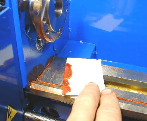
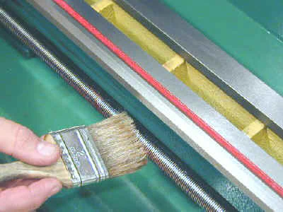
Next, use paper towels to wipe off the remaining visible layer of grease. Finally, use a chip brush dipped in kerosene or WD-40 to clean up the nooks and crannies where grease remains and then wipe the lathe clean with paper towels or cotton rags.
The easiest way to clean up the chuck is to immerse it in a pail of kerosene. First, use the chuck key to remove the chuck jaws. Then grasp the chuck with a paper towel or rag and remove the nuts from the back side of the spindle plate.
Use a chip brush to clean all of the red grease from the chuck, jaws and mounting nuts. When replacing the jaws, be sure to insert them in the proper sequence. The bucket method is also effective in cleaning up the toolpost.
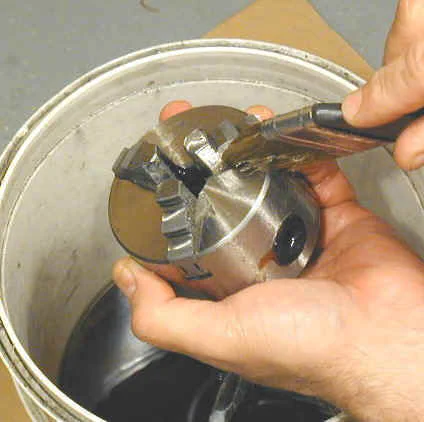
Crank back the compound handle counterclockwise until the locking bolts are visible (they are hidden under the top slide of the compound). Loosen the locking bolts and lift the compound off of the cross slide to clean underneath.
Then apply a thin layer of white lithium grease or light machine oil to the dovetail slides and leadscrews.
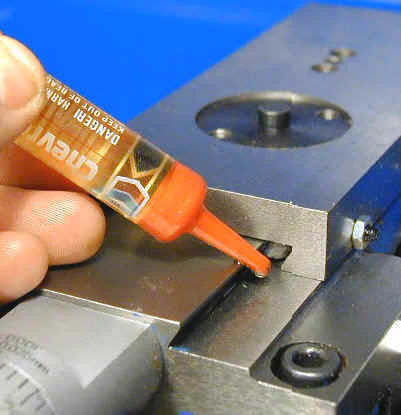
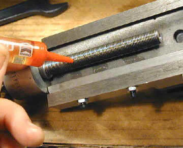
The cleanup procedure is the same as for any of the other lathes and has been documented in some detail on other pages so I will not repeat all of that information here.
Conclusion
A lathe is somewhat unique in the family of tools because you can do so much with it. A screwdriver drives screws, a hammer nails nails and a drill drills holes; but with a lathe you can make things. With the exception of my mini-mill, I can’t think of any other tool that I find so enjoyable to use.
If you have read this far, you have a pretty good idea of the features and construction of this little lathe. While not in the same league of quality as the classic American-made lathes made in the first half of the 20th century, this lathe is an outstanding value.
With proper care and adjustment, is a very capable machine.
But don’t just take my word for it. Visit the 7x interest group on Yahoo, and you can benefit from the experience of over 2000 others who are bound together by their common interest in the 7x mini-lathes.
As an active member of this group for several years, I can assure you that my experience and opinions are representative of many other owners.
I have to admit: after working with several 7x lathes over the last few years, I have developed a real appreciation for them. It was not always so.
The first few months with my first 7x10 were frustrating. It had been quite a few years since I had last used a lathe, and I really had to start from the beginning to learn how to use it.
These lathes have their quirks and limitations, and I had to learn them all the hard way. If you buy one, you may feel the same way at first, but stick with it.
Before too long, you will find that you can make just about anything that the lathe is capable of. That’s a very rewarding feeling and a great enhancement to your shop’s capabilities.