Making a Chuck Back Plate
On this page
- Spindle Plate Mounting Holes
- Time, Skills and Tools Required
- Cutting the Rough Stock
- Laying Out the Bolt Hole Circles
- Calculating the Bolt Hole Positions
- Marking the Bolt Hole Positions
- Bolt Hole Placement - Alternate Method
- Center Drilling the Bolt Holes
- Tapping the Bolt Holes
- Making the Mounting Studs
- Mounting and Centering the Back Plate
- Making the Center Hole
- Making a Spindle Plate Template
- Boring the Spindle Recess
- Facing the Back Plate
- Turning the Back Plate Diameter
- Drilling and Counterboring the Chuck Mounting Holes
- Turning the Chuck Recess Mating Area
- Mounting the Chuck on the Back Plate
LMS now offers a ready-made backing plate, item 1692. I have not evaluated it, but it looks like a much simpler alternative than making one from scratch.
The stock chuck and certain optional 3" chucks mount directly to the spindle plate of the 7x10 and 7x12 mini-lathe. Four-inch chucks, the largest I recommend using on the minilathe (Update 04/07: I later tried a 5" 3-jaw chuck.
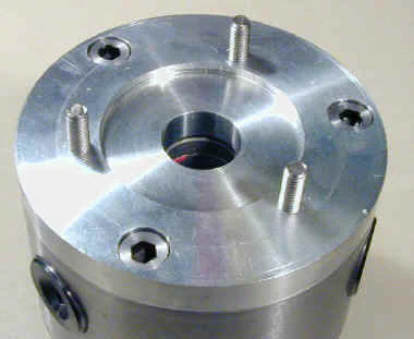
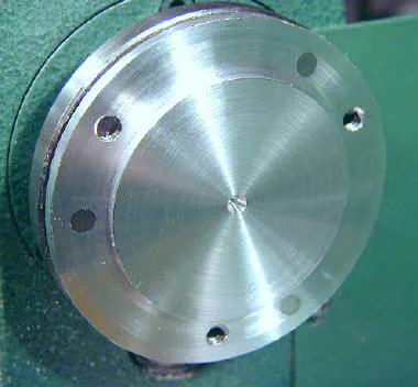
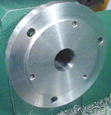
Although it is a little large, I have been using it now as my main chuck for several years), require an adaptor back plate to mate with the spindle plate. In this article, I will describe how to make a back plate to adapt a 4-inch chuck to the 7x10 or 7x12 mini-lathe. Specifics are included for both 3-jaw and 4-jaw chucks. Here’s the finished plate for the 4-inch 3-jaw chuck:
Check out Ty Hoeffer’s site for additional info on chucks and back plates 1 & 2; I recommend reading Ty’s comments before starting out on this project. Some more relevant reading can be found on Peter Harrison’s web site.
Spindle Plate Mounting Holes
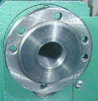
The Harbor Freight SKU 33684 7x10 lathe and the Grizzly 7x12 lathe have 6 holes in the spindle plate - 3 for the stock 3-jaw chuck and 3 more which, together with one of the other 3 holes, mate directly with the J&L 3-inch 4-jaw chuck.
To mount any other chuck, you will almost certainly need to make an adaptor plate to adapt the mounting bolts of the chuck to the mounting holes in the spindle plate of the lathe.
Note: the HF SKU 33916 7x10 lathe, some older versions of the HF SKU 33684 and the Grizzly Outlet 7x10 lathe have only 3 mounting holes in the spindle plate.
Time, Skills and Tools Required
Making an adaptor plate takes some time - probably 6-8 hours or more unless you are very skilled and know exactly what you are doing. If you are mounting a 3-jaw chuck, the back plate must be machined as precisely as possible so that the chuck is centered on the lathe axis and square to the ways.
Centering is not quite as demanding if you are mounting a 4-jaw chuck since the chuck jaws can be offset slightly to compensate.
For either chuck, you will need to lay out, drill and tap a number of mounting holes as well as a machine a carefully fitted recess for the lathe spindle and, most likely, a raised area to mate with a recess in the back of the chuck.
This combination of operations, plus the required precision, make the fabrication of a back plate a challenging project and one that is sure to make you think and work with care.
Properly done, though, it will produce a finely finished and very useful tool that you can admire for the life of the lathe.
If you are fairly new to machining, you may want to leave this project till a later time when you have gained some experience or you may find it very frustrating. Meanwhile, if you need a 4-jaw chuck, the J&L 3-inch 4-jaw mounts directly to the spindle plate without requiring a back plate.
For the benefit of those readers who have limited shop capabilities, I was hoping to make the back plate entirely on the lathe but I ended up using a drill press as well.
The drill press was used only for drilling the mounting holes. This could be probably done on the lathe if you have or make a faceplate so that you can offset the back plate to drill the holes, or mount the back plate to the cross slide on an angle plate.
Some operations, such as counterboring the mounting holes for the chuck, could have been done more easily using my Grizzly mini-mill, but I wanted to present a plan that would work for lathe owners who have only the stock lathe and a drill press.
You will also need a few other tools:
- Boring tool and holder (can get by without this)
- Dial test indicator (for precise centering and testing concentricity)
- Taps (1/4-20 or 6x1 mm) and tap wrench
- #0, #1, #2 center drills
- 1/2" 2-flute end mill (for counterboring bolt holes)
- Parting tool (for making studs from bolts)
- Dial caliper (to measure everything)
- Dividers (can get by without them)
- Bandsaw :) or hacksaw :( (for cutting the raw stock)
- 3 or 4 1/4-20, 1/4-28 or 6x1mm studs about 7/8" long, or bolts that you can make them from
Cutting the Rough Stock
I cut a piece of 1/2" thick aluminum plate down to 4 1/4" square on my 4x6 bandsaw. If your saw is accurate and you measure carefully you can save yourself some turning down to size later on by starting with a 4" square, but 4 1/4 gives you some margin for error.
Some time ago I added a vertical guide plate to my bandsaw to facilitate cutting plate stock.
This could be done with a hacksaw, of course, but the bandsaw makes a much easier job of it. I have also cut aluminum plate on my radial arm saw using a carbide tipped blade and making multiple passes increasing the cut depth about 1/16" on each pass.
Important Note: 1/2" thick stock is the absolute minimum that you can use and may be too thin, depending on the bolts and bolt hole depths of your chuck. 5/8" would be better, but 1/2" is more likely to be on hand in your shop.
Another good alternative would be to start with a piece of 4" round stock about 9/16" or 5/8" thick. A good solution would be to purchase about a 2" length of 4" diameter 6061 Aluminum round stock (assuming that you have a bandsaw to cut it down to 5/8" thickness) You can buy it for about $8 per inch from Metalmart.com I used the 1/2" plate because I had a good supply of it on hand.
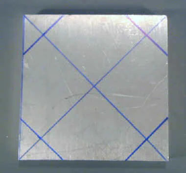
After cutting out the 4 1/4" square, mark the center and mark out the corners at 4 1/4". Then saw off the corners to make an octagon.

Laying Out the Bolt Hole Circles
Once you have your workpiece, locate the center point and make a small indentation there using a punch or a #0 center drill. Next, we lay out a bolt circle to match the 3 mounting holes in the spindle plate used by the stock chuck.
Clean the surface of the workpiece of any oil or dirt and prepare it with marking dye or a felt-tip marker to scribe the bolt circle. Using dividers or the points of a dial caliper, accurately mark out a circle of 1.299" radius.
It is easier to use dividers to scribe the circle than to use the points of the dial caliper. Also, I don’t like to use the points of the caliper for this since they aren’t really intended to be used in this way.
Since it is difficult to set the dividers to an exact setting such as 1.299, I first use the dial caliper to mark a small arc, then set the dividers to match this arc exactly.
Note: on the diagram on Ty’s site, the radius is specified as 1.293". The value specified in the manuals that came with all three of my chucks is 1.299 and careful measurements on my lathe showed it to be 1.305.
Ty and I have exchanged email about this and his viewpoint, clearly stated on his template instructions, is that you must measure your own lathe, since there are variations from machine to machine. Unfortunately, this is a difficult dimension to measure accurately. 1.300 is probably a safe value to use if you are unsure.
Next, scribe a circle 1.654" in radius for the chuck bolt circle. This corresponds to a diameter of 3.307" as specified by the manual that came with my 4" chucks but may be different for your chuck.
Calculating the Bolt Hole Positions
Note: an alternate method for locating the spindle stud holes is described a little further down the page.
Next we need to mark 3 (or 4, for a 4-jaw chuck) evenly spaced points on the spindle bolt circle. You can use a dividing head or rotary table if you have one, but if not, you can measure and mark the points using a dial caliper and divider.
There’s a simple formula for determining the distance between holes of a bolt circle.
> B = D x sin( 360 / (2 x N))
where
> B = distance between bolt holes
> D = diameter of bolt circle
> N = number of holes in circle
For the inner spindle plate bolt circle
> D = 2 x 1.299 = 2.598, N = 3, B = 2.598 x sin (360 / 6)
> B = 2.598 x sin 60, = 2.598 x 0.866, = 2.250
For a 4-jaw chuck (4 mounting bolts)
> D = 3.307, N = 4, B = 3.307 x sin (360 / 8)
> B = 3.307 x sin 45, = 3.307 x 0.707, = 2.338
For a 3-jaw chuck (3 mounting bolts)
> D = 3.307, N = 3, B = 3.307 x sin (360 / 6 )
> B = 3.307 x sin 60, = 3.307 x 0.866, = 2.864
Note: 3.307 is the bolt hole diameter specified in the data sheets that came with my chucks. If your chuck uses a different bolt circle diameter, plug that value into the equations above.
Marking the Bolt Hole Positions
Pick any point on the circle as a starting point and make a prick punch mark there. Make sure that the punch mark is right on the center of the line. Set your dial caliper to 2.250" and scribe an arc from that point to an intersecting point the circle. Now scribe an arc at a point on the other side of the circle.
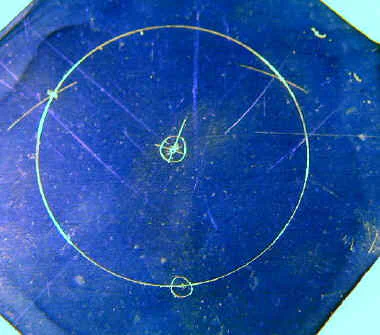
As a double check, position the caliper points between the points where the two arcs intersect the circle. They should be exactly the same distance apart as the caliper points.
If they are off by more than a few thousandths of an inch, you will need to repeat this process until you get it very close. It is important for every step be done very accurately or the bolts may not line up properly with the spindle or the chuck.
Now you need to repeat this procedure for the outer bolt circle. Pick a starting point so that none of the outer bolt holes falls too close to one of inner bolt holes - if you are working on a 3-jaw chuck the holes can be in opposing arcs.
Now set your dial caliper to the proper distance from your calculations, 3-jaw versus 4-jaw, and scribe marks as before.
Bolt Hole Placement - Alternate Method
Due to the difficulty of precisely locating the bolt holes by measurement and layout, an alternative is to make some little ’transfer punches’ out of steel on the lathe.
These little punches are then seated in the bolt holes of the spindle with the points protruding. On my lathe, at least, the spindle stud holes are slightly smaller in diameter at the back than at the front, so the little punches seat against the back edge of the hole.
You could probably make them longer and have them seat against the headstock if necessary. In the photo below, the short punches are for the spindle plate holes, and the longer ones are for the chuck bolt holes.
The second photo shows the punches in the spindle plate.
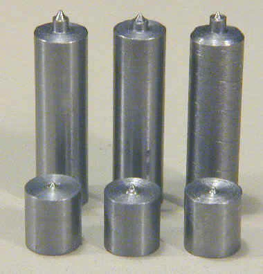
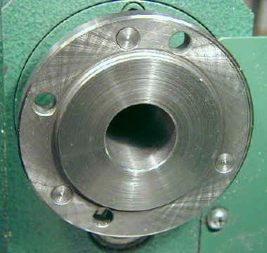
The dimensions are shown in the following table. Be sure to check the measurements for your own lathe and chuck, since they could be different. Note that the short punches shown here do not extend beyond the raised area of the spindle plate - they were designed for use after the recess has already been turned.
This presents a Catch-22 since you need the mounting holes drilled in order to mount the plate to turn the recess. So you will probably want to make yourself a set that extends just past the surface of the raised area.
Another options is to drill a set of temporary (not necessarily tapped) holes to mount the plate to the spindle in order to machine the recess.
| Short Punch | Long Punch | |
|---|---|---|
| Diameter | .270 | .258 |
| Height to shoulder | .285 | .908 |
| Height to tip | .320 | 1.010 |
Press the back plate into position on the spindle and tap the front of the plate lightly with a dead-blow or rubber mallet. This will leave little punch marks at the locations of the punch points.
Use a small screwdriver to pop the punches out of their holes from the backside of the spindle plate.
For the chuck bolt holes, first machine the land that mates with the recess in the chuck, then insert the punches into the bolt holes on the back of the chuck.
Place the plate on the chuck and tap lightly with a rubber mallet.
Center Drilling the Bolt Holes
Use a small (#0 or #1) center drill to make starting holes at each of the intersecting arcs and the center. Once again, it is important to locate these holes as precisely as possible.
Next, enlarge the holes with a #2 center drill. I hold the plate very loosely as the larger drill enters the hole so that the plate can move and center itself with the drill.
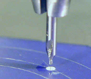
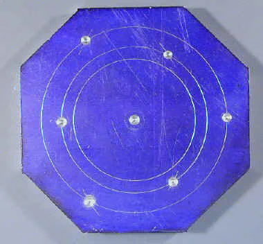
For maximum accuracy you could clamp the work down after centering the scribe mark and drill each hole out to its final size without repositioning it. This approach, however, requires many more operations to change the drills each time.
I opted for convenience instead and still achieved a result that was accurate enough.
Tapping the Bolt Holes
On the stock 3" chuck, 6mm studs are used. The holes in the spindle are large enough in diameter (.270) to accommodate 1/4" studs, however, unless you have a rotary table or are very experienced, I recommend using 6mm studs rather than 1/4".
It is very difficult to get the studs precisely on center with the spindle holes. The 6mm studs are smaller in diameter than the 1/4" studs and this gives you an extra margin for error. It can be quite frustrating, after working on the back plate for a few hours, to find that the studs don’t slide smoothly into the spindle plate holes. Trust me, I know ;-)
Now drill the 3 holes on the inner circle with the proper size tap drill (5mm or #9 for 6mm). Use a cutting fluid such as Tap Magic Aluminum to get a nice clean hole.
Here again, accuracy is critical. You want to make very sure that the tap is square with the surface of the plate. If it is skewed, the studs will be also, and may not mate with the spindle holes even if they are properly spaced.
I made a little tap guide on the lathe to ensure that the tap is square with the plate surface. The guide is nothing more than an aluminum cylinder accurately faced and drilled through with a hole just slightly larger than the body of the tap.
When starting the tap, I hold down on the top of the guide to keep it in place.
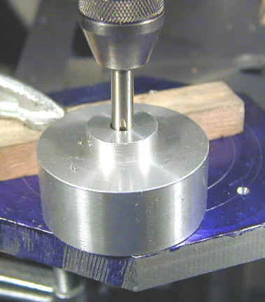
Here’s another trick to ensure that the holes are tapped square to the surface of the plate: Open the top of your drill press and disengage the drive belt.
Mount the tap in the drill chuck. Lower the tap down to the hole, apply pressure from the drill press handle and turn the drill press pulley by hand to start the tap into the hole.
Back off a quarter turn every so often to break the chip and make a nice clean thread. The main problem with this method, at least on my drill press, is that the return spring on the handle is fairly strong and has a tendency to lift the work up from the table, possibly defeating the purpose of this exercise.
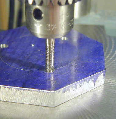
At this point, you may want to check these holes against the spindle plate to make sure they line up properly. If not, you may need to mark a new set of holes and try again.
Note that the bolt holes for the chuck do not need to be tapped. We will deal with them later.
Making the Mounting Studs
Next we will make 3 studs about 7/8" long by cutting the heads off 1/4" or 6mm bolts, depending on which you chose, using a parting tool. I got these stainless steel 6mm bolts and mating SS nuts from Small Parts, Inc., a good source for small quantities of parts.
It’s a good idea to protect the threads by making a sleeve from brass or aluminum:
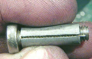
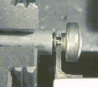
After parting off the heads, make a smooth facing cut on the end of the stud and clean up the end of the threads by filing them lightly at low speed at about a 45 angle.
Thread one of the studs into each of the tapped holes in the back plate and test mount it on the spindle using nuts.
Mounting and Centering the Back Plate
Screw the studs into the tapped holes a few turns and mount the workpiece on the spindle plate for facing. Later, we will bore the recess for the land on the spindle plate and, for that operation, it is essential that the recess be concentric with the mounting bolts.
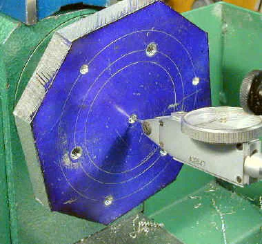
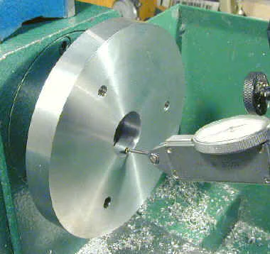
To ensure concentricity, carefully center the back plate on the lathe using a dial test indicator as follows:
- Tighten back plate nuts until just snug, then back off slightly (not loose)
- Position tip of dial test indicator (DTI) close to, but not touching, the center drill hole
- Turn lathe on at lowest speed
- Stop lathe when center hole is at highest point
- Tap top of back plate lightly with brass hammer or similar tool
- Repeat until centering is close enough to engage DTI
- Rest DTI tip on smooth side of center drill hole
- Use DTI reading to determine high point with spindle rotating
- Repeat centering procedure until runout is less than .001"; the closer the better
Making the Center Hole
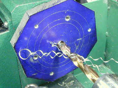
Now we are ready to drill out the center hole. The drill size is not critical but should be large enough to provide a starting hole for your boring tool.
I used a 3/8" drill. Mount the drill in the tailstock chuck and drill all the way through the backplate. Use cutting fluid for best results.
Use your boring tool to open up the center hole to about .875". The diameter is not critical, but don’t make it any larger than .900 or you will start cutting into the side of the spindle bore which is about .
920" in diameter at the face of the spindle.
Making a Spindle Plate Template
We’re going to digress for a while here to make a spindle template. We will need this a little later to machine the spindle recess on the back plate to precisely the right diameter.
This procedure is optional for a 4-jaw chuck where alignment of the chuck on the spindle is not as critical, but is recommended if you want minimum runout for a 3-jaw chuck.
Here’s what the finished template looks like:
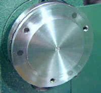
Basically, the spindle template simulates the raised land on the spindle plate. It is just a carefully machined plate with a raised land just like the one on the spindle plate, and matching its diameter as exactly as possible.
The template is used as a gauge for testing the diameter when you machine the spindle recess on the back plate. When you are turning the recess, the back plate is mounted on the spindle so you can’t use the spindle itself to test fit the recess.
Instead, you use the spindle template.
It is difficult to accurately measure the inside diameter of the recess to less than .001", but it is easier to measure an outside diameter accurately.
Additionally, when you turn the diameter of the template, you can test fit it into the back of the stock 3" chuck until you get a snug press fit. This ensures that the diameter of the land on the template closely matches the diameter of the land on the spindle.
On his web site, Ty Hoeffer describes how to make a spindle template. My version is simpler. Since I use it only as a gauge for the diameter of the spindle recess.
Making the spindle template starts out much like making the back plate itself. It can be thinner, though, and a 3" diameter piece of 1/4" aluminum plate is all you need in the way of materials.
If you start with a square piece of plate stock, cut off the corners just like you did on the back plate to form an octagon. Then mark the center and layout a bolt circle 2.199" in diameter, just as you did for the back plate. Scribe another circle 2.165" in diameter to mark the edge of the land area.
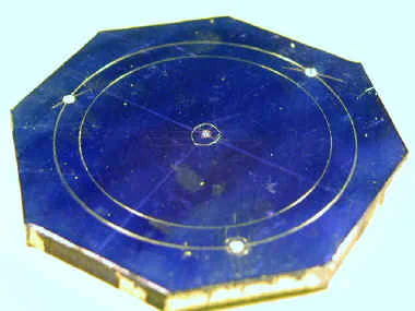
Use #0, #1, and #2 center drills in sequence to center drill the center hole and the three bolt holes. Then drill and tap the holes 6mm or 1/4". Mount the template on the spindle plate using 6mm or 1/4" studs, then carefully center it using a dial test indicator as described for the back plate.
The studs should only be screwed in about half the thickness of the plate or you will cut through them in the following facing operation.
Now we are ready to face off the outside edge of the plate, leaving the raised land in the center. The land should be 2.165" (check your spindle to be sure) and about 1/8" high.
Since the final diameter of the land is critical, first take a light facing cut and stop just outside the inner circle that you scribed. This marks out a rough guideline that you can work to without risk of overshooting and making the land too small a diameter.
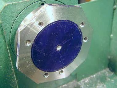
Note the extra holes are not necessary - they were for a technique I was testing.
Continue turning down the outside of the template stopping at the reference point until the land is about 1/8" higher than the surrounding plate. Make a nice smooth finishing cut.
Now, with the compound set at 0 degrees and the carriage locked in place, start removing a little metal at a time from the diameter of the land. Use a sharp pointed tool as you would to turn a shoulder, since that’s what we’re actually doing here.
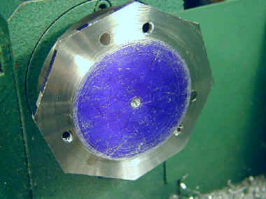
As you approach the target diameter of 2.165", take very light cuts leaving a smooth finish, Use the recess on the back of the stock 3" chuck to test for a snug press fit.
Use a file to champfer the sharp edge of the land just enough to remove any burrs. When the chuck will just barely fit over the land you are done with this operation.
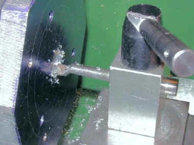
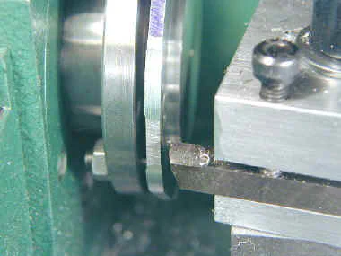
Mount a right-hand cutting tool outboard in the tool holder as shown below and use it to turn down and clean up the outside edge of the template. Use a rounded facing tool at about 1500 RPM to put a nice facing finish on the raised surface of the land.
Then you are done.
Boring the Spindle Recess
This operation is perhaps the most critical of all since the accuracy with which the recess mates with the raised land on the spindle plate will determine the runout of the back plate which, in turn, will contribute to the total runout of the chuck when mounted.
You will need the spindle template described previously to complete this operation so if you have not already made one, this would be a good time to do so, before you start this procedure.
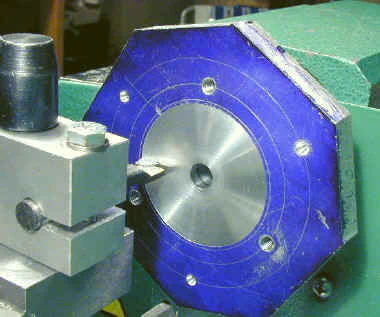
Take a light boring cut from the center hole out towards the outside edge of the plate. You want this cut to serve as a guideline for boring the recess, so stop at a diameter of about 2.100".
The remaining .065" will be removed very carefully after we get the recess bored out to a depth of about 1/8" (.125).
Instead of a boring tool you could use a ground HSS tool mounted in the back side of the toolpost. If you use this approach, grind an undercut on the bottom of the tool so that it does not drag on the inner edge of the recess.
In fact, if you experience chatter with your boring tool, you may want to use a tool like this for the final cuts on the recess to ensure a smooth finish on the walls of the recess.
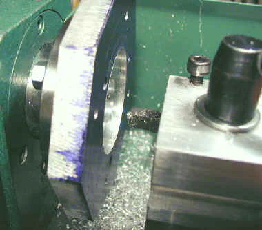
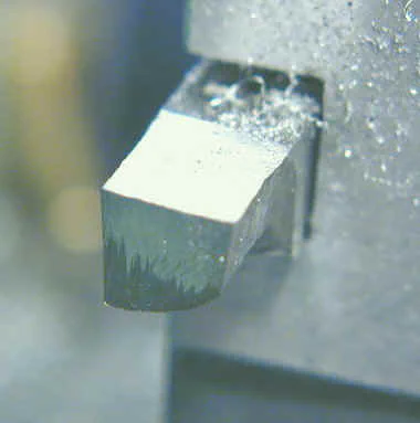
Take successive boring cuts of about .020 per pass until the recess is about .130" deep. Make the last cuts very light at about 1500 RPM to get a nice finished surface for the bottom face of the recess.
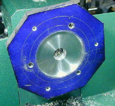
Now we are ready to bring the recess to its final diameter. This is a critical step and must be done very precisely without overshooting, so take your time, take small cuts and measure frequently.
When I’m working to a critical dimension like this I like to write the target dimension and each successive measurement in my shop workbook. This discipline helps to ensure that I don’t get impatient and remove too much metal.
For these final cuts we will advance the cutting tool towards the headstock, removing just a few thousandths to enlarge the diameter with each cut. Of course, since we are enlarging an inner diameter, the cross feed must be cranked outwards away from the lathe center on each successive cut.
Be sure to remove any backlash between cuts and remember that each cut removes twice as much metal as the number of divisions on the dial. For example, if you move the cross feed out by .002" on the dial, the diameter of the recess will be increased by about .004". Also keep in mind that the divisions on the dial are not exactly .001".
As you approach to within about .010 of the final diameter of 2.165", move the cross slide out a division or less at a time. Stop after each cut and measure carefully using the sharp points of the dial caliper and swinging them in an arc to make sure you are traversing the widest point of the recess.
After each measurement, try to press fit the spindle template land into the recess. When it just fits snugly, you are done with this operation.
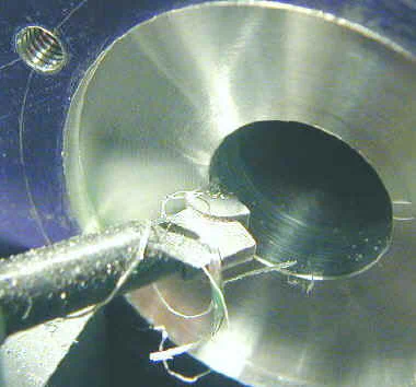
Turn your cutting tool to about a 45 degree angle and take a very light chamfering cut to clean up the sharp outer edge of the center hole.
Facing the Back Plate
Now we are ready to make a nice finished surface on one side of the back plate. One problem you will encounter here is getting the cutting tool to reach all the way to the edge of the plate.
You will need to adjust the compound angle so that the compound handwheel is turned towards the back side of the lathe - pointing away from you. With some fiddling with the toolpost angle you should be able to get the tool far enough out to reach the corner of the plate, or at least past the sides, which is good enough.
Face off only enough of the surface to get a nice smooth finish - remember, we don’t have a lot of extra thickness to work with. Use the boring tool to lightly chamfer the sharp edge of the recess.
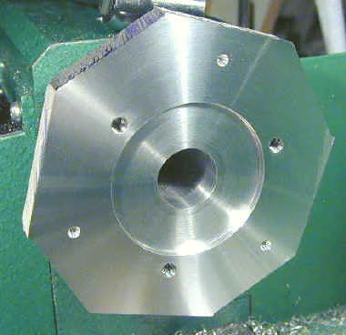
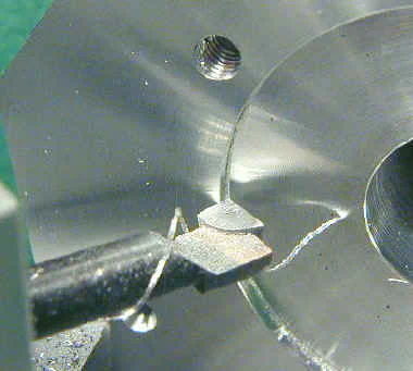
Remove the back plate from the spindle, remove the studs then flip the plate over and reinstall the studs on the opposite side. Mount the plate to the spindle seating the newly machined recess.
Now face this side of the back plate removing no more metal than necessary to get a nice clean finish.
Turning the Back Plate Diameter
Mount the plate back on the spindle and set up to turn the rough edges into a circle. A problem you will run into at this point is getting the cutting tool far enough out to turn the edge.
One option is to use a right hand cutting tool.
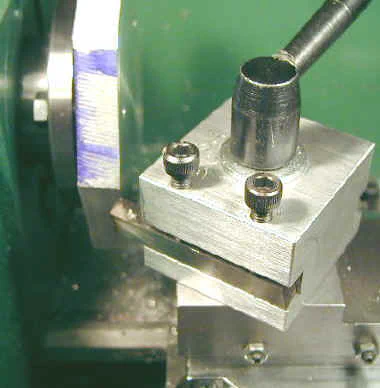
I use a special offset tool holder that I made for this purpose. A simpler version that I made before I had my mill is also shown.
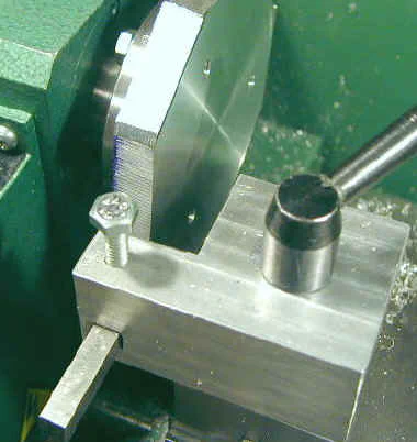
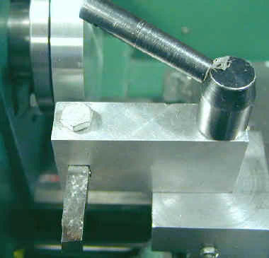
When you’re all done turning the outside edge this is a good point at which to test the runout of the plate. If all has gone well you would like to see a runout of 0.001" or less.
Drilling and Counterboring the Chuck Mounting Holes
Remove the plate from the lathe and place it on the drill press table with the recessed side facing up. Drill out the holes for the chuck bolts, that were previously center drilled, to 5/16" and finally to 21/64".
The heads of the chuck mounting bolts must be recessed into the back of the plate. The objective is to drill down so that the outside edge of the drill goes just a little deeper than the height of the bolt head.
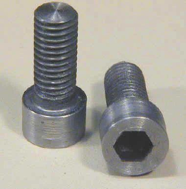
To get the bolt heads to fit these holes, I turn them down a little bit to a diameter of .465 and and height of .285. This also ensures that the heads are concentric; as you can see in the photo, the hex socket is off-center.
On my 3-jaw chuck, one of the bolt holes was not very deep so I turned about .050 off the end of the bolt so that it would seat properly.
These next drilling operations must be approached carefully since we are only drilling part way through the plate. If your forget this, and drill all the way through, you will not be pleased with yourself.
Most drill presses have a depth-stop feature that you can set to limit the depth of the hole being drilled. I used a piece of scrap about .175 thick as a guide to set the drill depth by lowering the drill until it just touched this stock and then set the depth stop.
Drill each of the chuck bolt holes out using a series of drills up to 1/2". I used increments of 1/32" for each drilling pass.
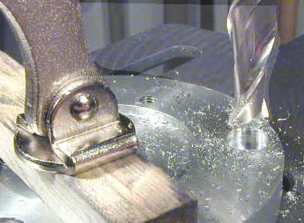
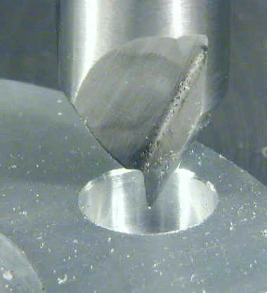
The final step is to use a 1/2" 2-flute end mill to flatten out the conical base of the bolt holes left by the drill. If you have one, of course, you should use a 1/2" counterbore for this operation; but they are an expensive investment if you use them infrequently.
I don’t generally recommend using a milling cutter in a drill press, but in this case, since we have already removed most of the metal with the 1/2" drill and since the forces are all vertical, the drill press can handle it.
The plate should be securely clamped to the drill press table for this operation, but before you clamp it down you must ensure that the hole is aligned with the drill spindle.
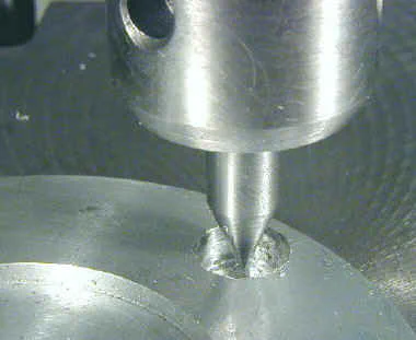
You can make yourself a little alignment tool by turning a cone about 1/2" long on the end of a piece of 3/8" drill rod. You could also use aluminum or brass as long as the cone is accurately concentric with the outside diameter of the stock.
Insert the alignment tool in the drill press chuck, then lower the spindle until the cone lines up in the bolt hole. Then lock the spindle to hold the plate in place and clamp the plate to the drill press table.
Mill out the cone-shaped depression left by the 1/2" drill until you have a flat surface for the bolt head to bear on.
If you have a large enough countersink, use it to put a nice finished edge on the bolt holes.
Turning the Chuck Recess Mating Area
Now we’re ready to turn down the outside edge, leaving a raised area to mate with the recess in the back of the chuck. Here again we want to get the diameter as close as we can to the desired dimension of 2.
834 as specified in the chuck documentation. Take a very light initial facing cut starting out the outside edge of the plate and stopping about 1/8" outside the stud holes.
This will be our reference point so that we don’t overshoot. Continue facing this same region until you have removed about .100".
Next we will take a little metal at a time off of the outside diameter of the raised land until we bring it down to exactly 2.834" in diameter. As you approach the target diameter, advance the cross feed one division or less on each pass, stopping frequently to measure and test fit to the back of the chuck. When the chuck just press fits over the raised land you are done. Use a file or lathe bit to lightly chamfer the sharp edge.
Mounting the Chuck on the Back Plate
Insert the mounting bolts into the counterbored holes and tighten them down. Make sure that the heads of the bolts are entirely below the back surface of the adaptor plate so that they will not interfere with the mounting of the plate on the spindle.
Screw the studs into the threaded holes and mount the chuck on the lathe.

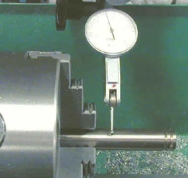
Now comes the moment of truth. Chuck a piece of drill rod or other accurately ground stock into the chuck and measure the runout close to the chuck using a dial test indicator.
Hopefully, you will see less than .001" runout, but .002-.003 is not too bad. Anything more than that is undesirable if you intend to use the chuck for any kind of precision work.
