Dolphin CAD CAM
On this page
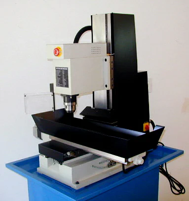
Back in 2007, I reviewed the Sieg KX3 CNC mill. I had intended to do a lot of work with the KX3, but demands from my day job, a few surgeries, new grandkids and preparing for retirement left little time to spend on CNC, so the KX3 sat in a corner of the shop, used only occasionally for milling a hole pattern or surfacing a plate in preparation for milling on a manual mill.
Now that I’m retired, and have more spare time, I want to put the KX3 to more productive use. In this article I’ll share the learning process I’ve been following to begin using Dolphin CAD/CAM software. My goal is to help other potential CNC users to understand how to get started down this path.
While there are many good demonstrations and learning aids available on YouTube, I did not find any that went through the entire process from drawing the part all the way through to machining it, tying all the different phases and operations together.
That’s what I hope to do here.
To make the process easy for beginners to understand, our project will be drilling four 1/4" diameter holes, evenly spaced, in a 2x3" x 1/4" thick aluminum plate.
>
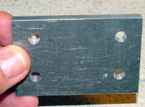
While simple, as far as CNC projects go, this project will introduce many of the basic concepts and procedures that you’ll need to know to get started. Here’s a short video clip showing the CNC drilling operation.
As most readers no doubt are aware, CAD/CAM software can be used to control many types of CNC machines, such as lathes, mills, routers, plasma cutters, etc. In this article, we’ll be looking at CAD/CAM software by Dolphin controlling the Sieg KX3 mill.
I’ll be starting from the perspective of the complete novice, which is pretty much what I am at this point in my CNC career. Dolphin is a good choice for home shop machinists as it combines a rich set of features with a low entry-level price. Special pricing is available for home shops and hobby users.
Before we get into the details, here’s a quick introduction to some of the terminology…
-
CNC stands for Computer Numeric Control. It basically means using a computer to control a machine tool, such as a lathe or a mill. A machine tool that can be controlled by a computer often is referred to as a CNC lathe, CNC mill, etc.
-
CAD is an acronym for Computer Aided Design and is the software used to design and draw the parts that you want to make.
-
CAM is an acronym for Computer Aided Machining or *Computer Aided Manufacturing.
-
CAM software specifies the tooling and machining operations to make a part defined by a CAD program.
-
CAD/CAM refers to the CAD and CAM used together.
-
CAD and CAM software usually are tightly coupled together and sold as a single software package.
-
GCODE refers to the computer instructions that control the CNC machine.
On modern CNC machines, GCODE usually is executed by a PC running Windows or Linux. The PC may be a standard desktop or even a laptop, but in industrial settings, usually is a specially constructed industrial-strength computer.
> 
If you’re interested in learning CAD/CAM operations, but don’t (yet) have a CNC mill, you can still move ahead. Free trial versions of CAD/CAM software from Dolphin and the Mach3 CNC controller software from Artsoft, a division of Newfangled Solutions, can be downloaded and used just as in a working environment - except for the final machining step.
However, since both software packages have visual simulations of the machining that will be done, you can get some useful experience even without a CNC mill.
OK, so let’s get started…
CNC Machining using GCODE
My biggest obstacle to using the KX3 mill to its full potential was that I didn’t have any CAD/CAM software. Therefore, I was limited to writing programs using low-level GCODE.
GCODE instructions direct the CNC machine to do whatever is needed to make the part being fabricated. Most GCODE instructions perform a simple operation such as positioning the workpiece at a specified X,Y coordinate, setting the spindle speed or lowering the spindle to drill a hole.
More advanced instructions, known as canned cycles, perform complex operations such as automated peck-drilling, or milling out a circular pocket.
Just to give you an idea what GCODE is like, shown below is a small program I wrote to finish the surface of a rectangular workpiece. The dimensions of the workpiece are specified by the parameters #101 (X) and #102 (Y).
I have chosen to use inch units, since all of my milling tools are in inch units.
Given the X,Y dimensions of the workpiece and the diameter of the end mill, this program makes as many passes back and forth across the surface of the workpiece as are needed to mill it to a smooth, even surface.
I’ve written other, more complex versions of this program that make a specified number of quick roughing passes followed by a slower-moving finishing pass at a higher spindle speed to get a really nice final finish.
G20 (Set inch units) F20 (Set feed speed) S3000 (Set spindle speed)
#101 = 1.2 (X dimension) #102 = 1.0 (Y dimension)
#201 = [5/16] (Tool diameter) #202 = 0.020 (Tool overlap per pass)
#301 = 0.005 (Depth of initial and incremental cut) #302 = 0.002 (Depth of final finishing cut) #303 = 2.0 (Height to raise tool at end of program)
#401 = 1 (Number of roughing passes) #402 = 1 (Number of finishing passes)
#501 = [#201-#202] (Effective tool diameter per pass) #502 = FUP[[#102/#501]+.5]
#601 = [#201 / 2] (Tool radius) #601 = [#601 + #202] (Add in overlap)
#901 = 0 (Current x position) #902 = 0 (Current Y position) #903 = 0 (Current Z position) #904 = 0 (Toggle for X direction) #905 = #101 (Length of X pass)
% Move tool off edges of workpiece #901 = [#901 - #601] (Offset X starting point by radius + overlap) #902 = [#902 - #601] (Offset Y starting point)
G0 Z 0.2 (Raise tool) G0 X#901 Y#902 (Move to starting location)
#903 = [#903-#301] (Lower tool by incremental amount) M3 (Start Spindle) G1 Z#903 (Lower tool) M98 P2001 L#502 (Loop for each pass) M5 (Stop spindle) %G0 Z #303 (Raise tool) g0 Z#303 X0 Y0 (Move to starting location) M30 (End Program and rewind)
%========================================================= O 2001 (Subroutine - make one pass) #902 = [#902+#501] (Y increment) G1 Y#902 (Advance by Y increment) #904 = [#905-#904] (Toggle between 0 and X max) G1 X#904 (Make one X pass) M99 (Return) %==========================================================
Having been a computer programmer for about ten years of my career, back in the 70’s and 80’s, I’m used to commenting almost every line of code to explain what it does (or is intended to do).
Lines that begin with a percent sign, and text enclosed within rounded parentheses, are merely comments and do not perform any machining operations. The comments are there to help me, and anyone else reading the code, to understand how it operates.
Many GCODE programs you may find on the internet, and especially those generated by CAM programs, may have few comments or no comments at all, and may combine several instructions on each line with no spaces in between, making them hard to decipher.
(Maybe that’s why they call it code?)
Some programmers seem to cram as many instructions as they can onto one line. My philosophy: try to make it as easy as possible for anyone who reads the code to understand what it does.
Back in the 70’s, it may have been true that comments slowed down the program execution, but with modern, high-speed CPUs I would be very surprised if that is true nowadays.
So why not make it easy to understand?
Programming in GCODE helps you to understand how a CNC machine operates, but it is a relatively slow and labor-intensive process.
One problem with GCODE is that it’s not very intuitive; the relationship between the part you are making and the cryptic instructions that you type to make the part is not always obvious (to me, at least!) Without consulting a reference manual, it’s unlikely that you’d guess that an M5 code stops the spindle rotation or that G5 sets inch units.
To ensure that the CNC machine does what you are intending for it to do, you must run many simulations and tests as more features are added to the program.
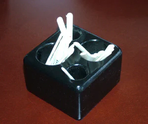
However, with patience and practice, you can make some useful parts, such as these holders I made from wood for my wife’s Mah Jong money sticks. Several of her Mah-Jong-playing friends have asked me to make holders for them.
Now that the GCODE program is written and tested, I can make copies of the holders, which come in sets of four, pretty quickly. Most of the time is spent sanding and painting.
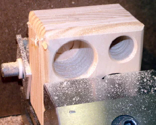
If you’re interested, here’s a link to a short video on YouTube showing the KX3 mill in action making one of these holders using a router bit to chamfer the hole edges. You may notice in the video that the spindle speed keeps changing. I believe that is caused by some process running on the laptop I’m using to run Mach3 to control the KX3 mill.
Some day, I hope to find and fix that problem. For reasons like this, ArtSoft does not recommend using a laptop as a CNC controller, so I probably should find a cheap, used desktop PC, running Windows 7, that will fit in the KX3 cabinet. (Long Live Windows XP!)
Another limitation of GCODE is that most instructions generally perform only a small piece of work. An operation such as cutting along an irregular curve takes many instructions, each one moving the cutting tool by a small segment along an arc.
Therefore, in most commercial shops GCODE programming has been superseded by CAD/CAM. GCODE still runs the machine - it’s just that the code itself is produced by the CAM software rather than being written directly by a person.
Introduction to CAD/CAM Software
In case you’re new to all of this, CAD is an acronym for Computer Aided Design and is the software used to design and draw the parts that you want to make. It functions much like a computerized drafting table, but has many powerful features to speed up and simplify drawing and to increase precision and reduce errors when making complex technical drawings.
Shown below is the Dolphin CAD screen with a drawing of a simple part: a 2x3" rectangle with four 1/4" diameter holes drilled in it. Note that the drawing provides no information about the thickness of the material, or the type of material to be used.
Although the part designer no doubt has already decided what those will be, that information is not needed at this stage.
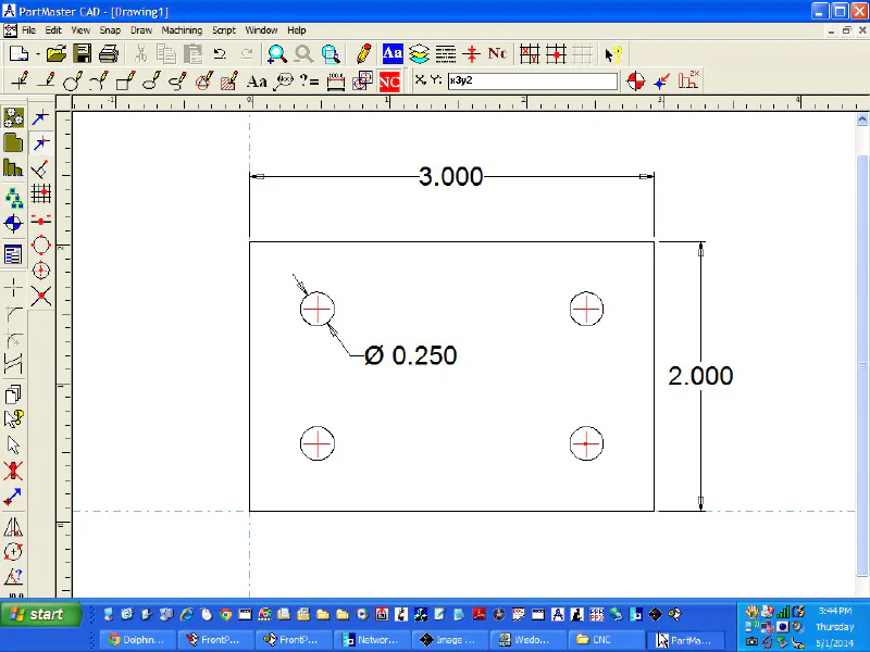
CAD programs produce output files which can then be further processed by a CAM (Computer Aided Machining, or Computer Aided Manufacturing) program to generate the GCODE instructions needed to run the CNC machine to make the parts.
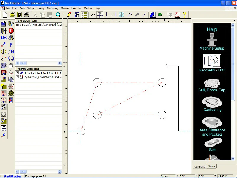
The screen below is the Dolphin CAM screen specifying the machining operations for the part shown above.
If you need to make only one part, or perhaps two or three of the same part, chances are you could do that on a manual mill as quickly as by using CAD/CAM.
That’s because of the time it takes to draw and specify the part using CAD, then refining the instructions using CAM so that the mill knows the sequence of operations to follow and other specifics about the machine and tooling to be used.
On the other hand, if you need to make four or more fairly complex parts that all are exactly the same, you are getting into the area where CAD/CAM and CNC machining excels. Especially on long production runs of complex precision parts, there’s simply no way that even a seasoned master machinist can compete with CAD/CAM and CNC.
Just like in the legend of John Henry and the steam-powered hammer, there’s a point at which machine wins out over man. On the plus side, though, this arrangement lets the humans focus on what only they can do: envision and design a system of parts into a functioning product, while the CNC machines perform the laborious, repetitive (and potentially dirty or hazardous) machining jobs.
Besides the advantages of speed and consistent accuracy, CAD/CAM enables you to make complex, curved cuts that would be difficult and very time consuming to do manually.
The X-Y-Z structure of manual machine tools makes them easy to control when making smooth, straight-line cuts along an axis, but machining complex curves using manual axis controls can be slow, difficult and error-prone.
With CNC, machining complex curves is routine and, in many cases, not much more difficult than machining straight lines.
So, the process of producing a finished part using CNC breaks down into several steps:
- Design the part using CAD software
- Specify the machining sequence and tooling using CAM software
- Convert the CAM output to GCODE for a specific machine using post-processor software
- Run the GCODE on the machine tool to make the part
The first two steps are largely machine-independent. From the outset, you must specify the type of machine that will be used, such as a lathe, mill, plasma cutter or gantry router, but if the part will be made on a lathe, as long as it is configured for CNC operation, it makes no difference at this stage whether the lathe is a South Bend, Logan, Hardinge, LeBlond, Monarch or Asian import, since they all share common basic operating principles.
The last step, running the GCODE, is done by software that is closely coupled to the machine, and has parameters set, such as the maximum distance for each axis, that are specific to the machine in use. On my KX3 mill, Mach3 software by Artsoft performs this service.
(Note: as of 04-2014, ArtSoft is nearing release of Mach4, a more advanced version of their CNC software)
>
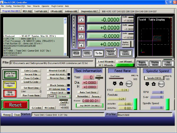
On most high-end industrial CNC machines, which may cost tens- or even hundreds-of-thousands of dollars, the controller software that executes the GCODE generally is developed, installed and supported by the machine manufacturer and runs only on that manufacturer’s machines.
CNC machines in the $12,000-and-under price range (2014 prices), more typically used by hobbyists and small shops, usually use Mach3 as the controller software.
Developed by ArtSoft, now part of Newfangled Solutions, Mach3 is unique in several respects. Priced at just $175 (04-2014) and thus affordable to a large market of hobbyists and small businesses, Mach3 was designed to be as machine-independent as possible.
Therefore, it can control not only a wide variety of commercially manufactured CNC machines, such as the Sieg KX3, but also can be configured to control one-of-a-kind machines that are built from scratch and are unique to the person or team who built them.
The machine’s operating parameters are specified when Mach3 initially is set up for a specific machine. It’s no surprise, then, that Mach3 dominates the market in controlling low-cost CNC machines typically used by hobbyists.
Layers of Software
One thing that I didn’t understand when I started learning CNC, was the layers of software involved. I had a simplistic idea that I could just draw a part using CAD, put a piece of metal in the milling vise, click an on-screen button and the mill would go to work making the part.
That would be nice, but it’s not quite that easy. When you think about it, it soon becomes apparent that there’s a lot more information, other than the part’s physical dimensions, that the machine must have in order to make the part.
When we machine a part using manual methods, we make many decisions throughout the process and perform many support functions, such as positioning the workpiece in the vise, zeroing the tools, changing tools for various operations, and so forth.
For an experienced mill operator, these actions become almost second-nature, so you don’t necessarily think about all of the steps involved when you’re making a part.
When you use a CAD/CAM system, you must define these steps as parameters in the machining process before you can start cutting, so that the machine will know what to do.
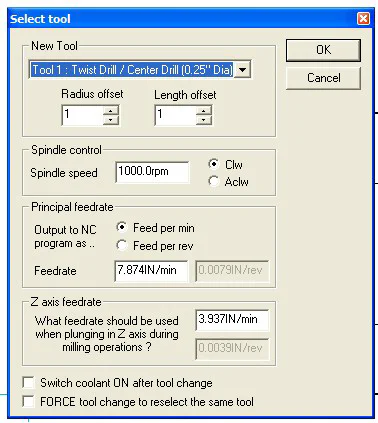
For example, shown below is a screen from Dolphin CAM where I have specified the parameters for a center drill. This information is stored as part of the tool definition and sets operating parameters such as the diameter, length, spindle speed and feed rate for the tool.
If the feed rates seem arbitrary, it’s because Dolphin calculates them using metric units by default. In future versions of Dolphin, that may be changed to conform to the units selected.
>
While the various layers of software are designed to work seamlessly together, it is possible, and often useful, to use certain features of the layers independently of the other layers.
For example, if you need to make a technical drawing of a part to communicate the specifications to a partner located in another state or country, you could make the drawing using CAD software and email the resulting specification file to a remote recipient who could view that part using CAD software that is the same as (or similar to) the software used to create the file.
Most CAD software can share certain standard file formats with CAD software from other vendors. The remote partner could then make changes to the file and email it back to you, enabling a collaborative design process.
Or you might have a designer or design team at one location, while the machinery to make the parts is at another location. Only the control files need to be passed from one shop to the other.
Sometimes, a drawing may not be needed, so you can skip the CAD step and go right to the CAM program. Certain procedures, such as drilling a bolt-hole circle, milling the surface of workpiece to make it flat or machining a circular pocket are encountered so often that it’s useful to be able to perform them without first creating a drawing of the part.
For situations like this, the Dolphin CAM software has built-in procedures that let you quickly and easily enter the parameters for the part, and then execute the resulting GCODE without having to make a drawing at all.
>

In fact, even the Mach3 software that controls the machine has features for similar operations, allowing you to bypass the CAM software as well as the CAD software.
And, as we’ve already seen, there are times when coding a GCODE program manually, using nothing more than a text editor, is all that’s needed.
Learning CAD
Learning a CAD program can be like the proverbial “drinking from a firehose”. There are so many features and options, that it can be daunting at first to know what to do next. In my case, I think that the process may even have seemed more complex because I was already experienced using another simple CAD program: Delta CAD.
I’ve been using Delta CAD for quite a few years. It’s great for making simple drawings, especially when working out detailed dimensions for a new part with tight tolerances.
It’s inexpensive and easy to learn, but does not have the richness of features found in Dolphin CAD, nor does it interface seamlessly to a CAM system like Dolphin does.
As you might expect, each program has its own way of doing things, so there’s a certain amount of “unlearning” and “relearning” that goes on when switching from one program to the other.
Another factor is that I’m now 64, and apparently don’t catch on to new ideas as quickly as I did when I was younger. Fortunately, there are a lot of videos on YouTube that explain and demonstrate the basic features and functions of Dolphin CAD.
When I got stuck, I watched the videos while following along with the same drawing on my own computer until I got the hang of it. Like most things in life, repetition and practice help you to nail down your skills, so don’t get discouraged if you find the going rough in the beginning.
I’m not aware of any CNC hobbyist groups where I’m located near Richmond, VA, so I’ve had to learn CNC on my own by trial and error. Mostly error. I suspect the learning process would have been a lot quicker had an experienced Dolphin CAD/CAM user been available to instruct me.
So, if you’re an experienced CNC user, don’t be surprised if you find that some of the advice that I offer here is not aligned with best practices, or even standard practices.
On the other hand, the information is free, and probably worth it.
Drawing a Simple Part
I like to learn by doing, so let’s get started by drawing a very simple part: a rectangular plate of material with four holes of the same diameter. The actual material that the part will be made from, aluminum, steel, brass or acrylic plastic, makes no difference at this stage of the process.
However, it will matter later on, when we must specify the machining feeds and speeds.
Dolphin CAD and Dolphin CAM actually are two separate programs sold together as a system. As discussed above, they can be used independently of each other, but they’re closely coupled so that a part that you draw in CAD can be passed seamlessly to CAM to specify the machining operations.
For now, we’ll focus just on drawing the part using CAD.
I’m going to assume that you already have downloaded a copy of the Dolphin CAD/CAM software from the Dolphin web site and have installed it on your computer.
This is a fairly quick and simple operation as long as you have a high-speed internet connection. Dolphin allows you to download and install the software initially at no cost, so that you can can evaluate it for 90 days to ensure that it will meet your needs.
At any time during or after the 90-day trial, you can purchase the software online and activate a license.
When you start the Dolphin software, you should see a screen similar to this:
>
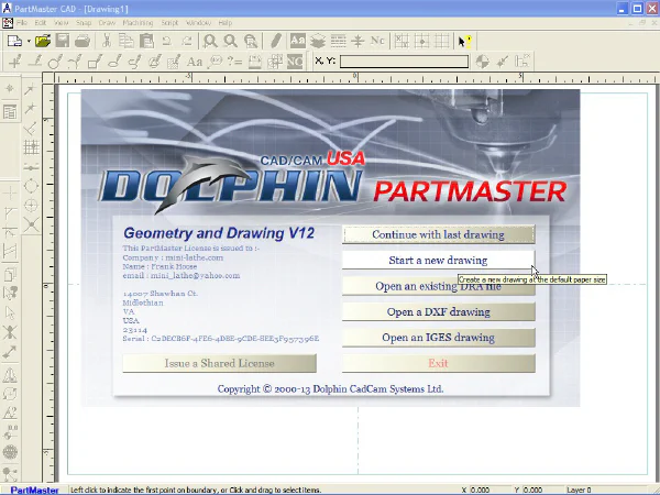
Select Start a new drawing from the menu; now the drawing area should have dashed cross-hairs with a red dot in the middle.
>
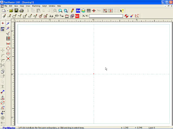
You’ll notice a number of toolbars along the top and left edges of the screen. On your computer, they may be arranged differently than in the examples.
You can arrange the toolbars however you like them - just grab the end using the left mouse button and drag them where you want them. They’ll anchor to the top or left side of the screen, or you can leave them floating anywhere on the screen.
On the drawing toolbar, you select the type of object you want to draw, such as a Point, Line, Circle, Arc, Box, etc.
>

You may notice that when you select an object type from the drawing toolbar, the icons and choices on the secondary toolbar (on the left side of the screen in this example) change - they’re context sensitive to the type of object being drawn.
In the example below, I’ve selected Box from the main toolbar, then I can choose Normal Box, Iso Box Top, Iso Box Left, etc. from the secondary toolbar.
>

The workpiece that we’ll machine will be rectangular, 2x3" in size. Click on the Box icon, then move the cursor towards the center of the drawing area.
(also click Normal Box if you have another type of box selected) You’ll see that the cursor changes to a cross-hair shape,
>
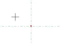
and at the bottom left of the screen you’ll see the message:
>
![]()
When you click the left mouse button, it anchors the first corner of the box at the current cursor location. Now the message at the bottom of the screen reads
>
![]()
Now when you move the cursor, you’ll see that the box stretches. You can stretch the box in any direction around the anchor point that’s been established.
>
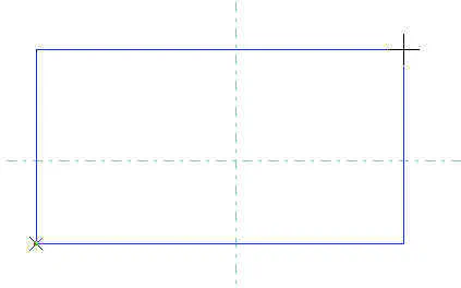
As the box stretches, the coordinates displayed in the lower right corner of the screen change accordingly.
>
![]()
If you click the left mouse button again, it locks in the upper right corner of the box at the current cursor location. If the box is not the size you want, click on the Undo icon on the top toolbar, or press the Ctrl and Z keys at the same time (you probably already know this, but Ctrl-Z is a standard key sequence meaning undo in many Windows programs).
You could try to move the cursor carefully until the coordinates read X 3.000, Y 2.000, but that could very tedious. Instead, move the cursor into the text box at the top right of the screen labeled X, Y: and type x3y2 followed by the Enter key.
>

You should now have a 3 inch by 2 inch box displayed.
>
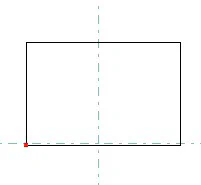
*Tip: as you’re experimenting, you may find that the screen becomes cluttered with unwanted objects or lines. If that happens, click on the pencil (Redraw) icon on the top toolbar to redraw a fresh and clean image.
>

You can also use Ctrl-Z or the Undo button to erase previously drawn objects one at a time.
Let’s erase the box that you just drew and try something new. Click on the Undo button to delete the box.
>

This time, we want to anchor the lower left corner of the box to the red dot in the middle of the screen, known as the datum. The datum point is the X0,Y0 reference point for the part.
Often, it’s helpful to think of the screen as having an underlying X-Y grid on which the part diagrams are overlaid. In fact, you can display such a grid for situations where it’s useful, but we’ll save that trick for later.
For now, we just want to learn a concept called snapping to a point.
As you could see by watching the coordinates change as you moved the cursor, it’s very difficult to position the cursor to an exact point, accurate to three decimal places.
For that reason, CAD programs have a feature called snap that automatically “snaps” the cursor to the nearest point or intersection. We’ll use that feature now to snap the starting corner of the rectangle to the datum.
There actually are several snap modes. For now, we want to use Near Snap, which snaps the cursor to the nearest point.
>

Click on the Near Snap icon. Now, as you move the cursor near the datum at the center of the drawing area, you’ll notice that cursor “locks on” to the red dot.
After the first left click, move the cursor into the X, Y: text box.
>

The x3y2 entered previously should still be there, so you can just press Enter to complete the drawing of the 3x2 box.
>
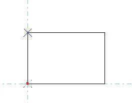
So now we’ve completed drawing the shape for the outline of our 2x3" workpiece. Next, we’ll draw the locations for the holes to be drilled.
Drawing the Holes
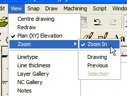
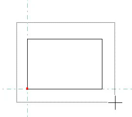
First, let’s Zoom In on our drawing to make it larger. On the main menu, select View, then Zoom, then Zoom In. Move the cursor near the upper-left corner of the box that was drawn, left click, then drag the outline around the box.
When you release the left mouse button, the view will zoom in on the region that was outlined, making the box fill more of the drawing area.
>
We want the four holes to be evenly spaced on the surface of our plate. To facilitate their placement, we’ll draw some temporary construction lines to serve as placement guides.
Select the Line tool, then, from the sub-menu, select Parallel Line
>


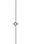
Now move the cursor over to the vertical line that forms the left side of the 3x2" box. You should see a cross-hair cursor with a small square in the middle.
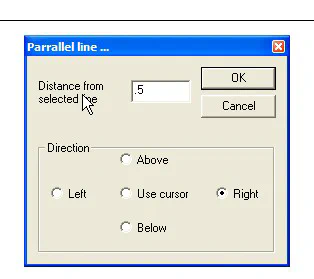
When the cursor is over the vertical line, click the left mouse button and a window will pop up. Enter 0.5 in the dialog box, then click on Right radio button in the lower part of the window.
A new line will be drawn parallel to and 1/2" inch to the right of the left edge of the 3x2" box.
>
>
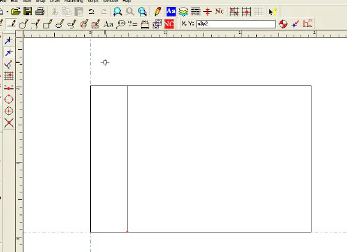
Now move the cursor over the right edge of the 3x2" box and repeat, only this time specify Left for the parallel line offset. Repeat this procedure again for the top and bottom edges of the box, using the Above and Below options.
When you’re done, you should have four new lines:
>
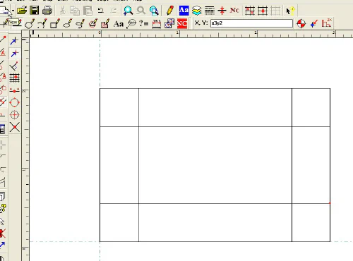
Now that we have our construction lines in place, we can draw the circles representing the 1/4" drilled holes at the intersections.
>
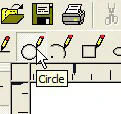

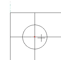
Select the Circle tool and the Normal option. Position the cursor over the intersecting lines near the top left corner of the 3x2" box. You should see a circle surrounding the point where the lines cross.
To be able to draw circles at the intersections of our construction lines, click on Intersect
>

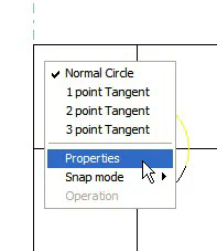
Left click and a red dot should lock onto the intersection. The circle may be larger or smaller than the 1/4" diameter that we want. Right click on the circle and select Properties from the pop-up window.
Now enter 0.25 as the diameter for the circle, then click OK.
>
>
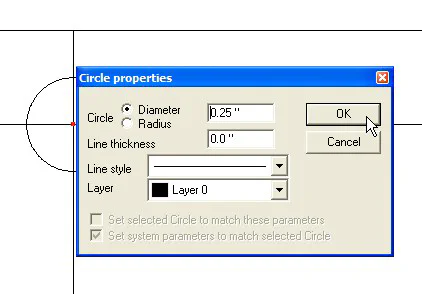
Move the cursor over each of the remaining three intersections and Left Click on each one. A 1/4" circle will be drawn at each intersection.
>
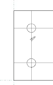
Since the construction lines have now served their purpose, they are no longer needed and can be erased. To erase them, select the Delete tool (looks like an exclamation point with an X through it).
Move the cursor (which now displays a small eraser) over each of the construction lines and left click.
>

>
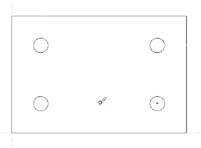
At this point we have completed the basic drawing of our plate with four 1/2" diameter holes. Now we need to begin defining the machining operations.
Drawing the Machining Contours
Within Dolphin CAD/CAM, a contour is a continuous line around an element in the drawing. In our example, it could be the outline around the outer edges of the workpiece, and around each of the holes to be drilled.
Contours direct the milling machine where to cut, drill or mill. Contours must be drawn around each of the elements in your drawing for which a machining operation will be performed.
Later, in the CAM module, the sequence in which those cuts will be made, along with information such as drilling depth, spindle speed, feed rate, etc.
will be specified.
It turns out that you can define contours either in the CAD module or in the CAM module. In this example, I chose to do it in the CAD module.
Click on the red NC icon, located near the Redraw pencil icon. A new set of toolbar options appears. Select the NC Contour icon.
>
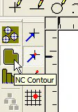
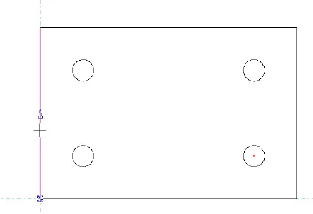
Now move the cursor over the lower left edge of the box near the center of the drawing window. As the cursor approaches the box, the appearance of the vertical side of the box changes.
The blue vertical arrow shows that the contour will be drawn in a clockwise direction around the box. Left-click the mouse and a new dialog box appears.
>
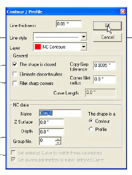
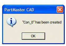
For now, just click OK to accept all of the default values. Note that the contour is assigned the name Con_0. The contour will then be drawn in red all the way around the perimeter of the box and a new dialog box will appear.
Click OK again.
>
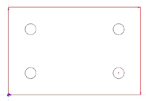
Strictly speaking, we don’t really need to draw this contour since we won’t be cutting the workpiece out from an oversize piece of material. The contour is needed only to guide a cutting operation.
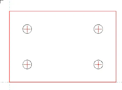
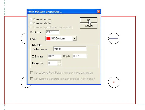
Now we need to define the four holes for machining. Select the Pattern icon from the NC toolbar. Move the cursor over the upper left circle, representing a 1/4" hole to be drilled, and left click.
Simply click on OK to accept all of the default parameters. Now move the cursor and left-click on each of the remaining three holes. You should see a red cross-hair pattern at the center of each circle.
This procedure links the four holes together as a Pattern, named Pat_0, so that they can be machined together using the same tool and feeds.
>

>
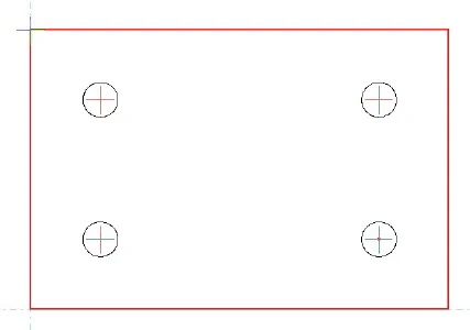
At this point, we’re done defining the contours and patterns and ready to move to the CAM module.
Specifying the CAM Operations
Now that we’ve finished drawing the workpiece in the CAD module, we switch to the CAM module to define the cutting tools that will be needed, the machining operations such milling and drilling, and the spindle speeds and feed rates.
To exit from CAD to CAM, select Machining from the main menu bar, then Milling Module.
>
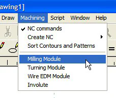
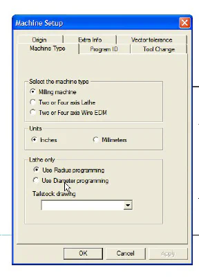
Within a few seconds, the CAM screen should pop up. One of the first things you’ll see is the dialog box for Machine Setup. For now, all you need to specify is the machine type Milling Machine and the units Inches (use inches for consistency with our CAD drawing.) You don’t need to make any entries on the other tabs at this time.
>
Defining Tools
The only operation that we’ll perform is drilling the four holes. First we need to define our tooling, which, in this case, will be a 1/4" diameter twist drill. Normally, I’d first use a center drill to start the holes, but for simplicity we’ll skip that step. Instead I’ll use a short, stiff 1/4" screw-machine drill bit, which is unlikely to flex or drift away from the center of the hole location.
In the upper left corner of the screen you’ll see a small sub-window labeled Tooling Definitions.
>
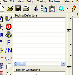
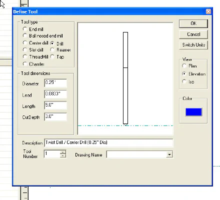
First, we must define the parameters for our cutting tool, which, in this case, is a 1/4" diameter short-shank twist drill. Select the Tool icon from the menu and a Define Tool window will pop up. Click on the Drill radio button and enter the diameter as 0.25 then click on OK.
Since we’ll be manually zeroing the tip of the drill bit to the workpiece, it really doesn’t matter whether or not we accurately enter the length of the drill bit - the tool dimensions, other than the diameter, are required only if calibrated tool holders, such as the Tormach Tooling System, or an automatic tool changer, will be used.
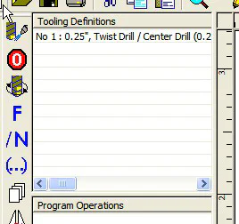
The 1/4" drill bit now appears in the Tooling Definitions list.
>

>
Defining the Drilling Operation
The Tooling Definitions list is like a catalog of available tools. In our case, we’ve defined only one tool, but in a typical machining scenario, there would be several tools defined, such as center drills, end mills, twist drills and chamfering tools, in various diameters.
Below the Tooling Definitions sub-window is the Program Operations sub-window. Our first program operation will be to select the 1/4" drill bit from the tooling definitions.
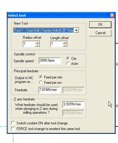
Click on the Select Tool (M6) icon. In the pop-up window that appears, we see the 1/4" drill bit listed as the New Tool. If multiple tools had been defined, we could select the desired tool from the drop-down list, but in our case, there’s only one tool to choose from.
Down below, enter 2500 as the Spindle Speed. Of course, the spindle speed you enter will depend on several factors such as the workpiece material, tool diameter, tool material (e.g. HSS vs Carbide), etc. The same is true for the feed rates, which, for now, we will leave set to the default value.
>

Next, we define a machining operation for the tool we just selected. Click on the Drill icon.
>
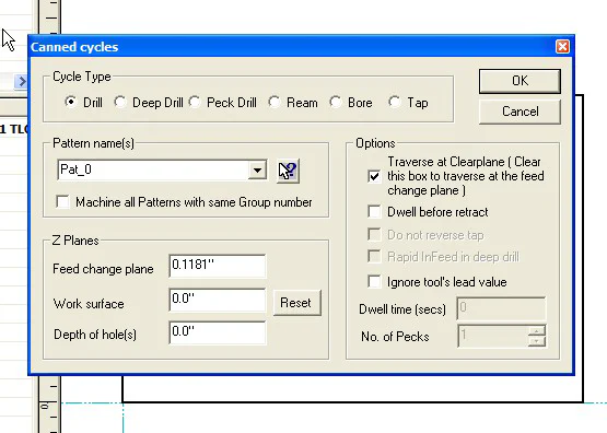
Earlier, in the CAD module, we defined a drilling pattern for the four holes. Dolphin CAD assigned a default name, Pat_0 to this pattern. Since the four holes are linked together by the pattern, they will all be drilled in sequence using the same tool, spindle speed and Z-axis feed rate.
Click on OK to accept all of the default values for this window. The CAM screen now looks like this, showing the sequence in which the holes will be drilled.
>
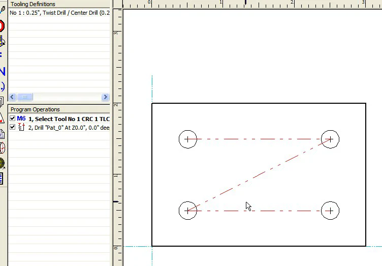
By the way, if you need to change a tool definition or program operation, just double-click on the corresponding line in the sub-window to bring up the editing window.
If you right-click on the line, you can delete or copy/paste the line.
Since we have no other machining operations to define, we’re ready to generate the GCODE. Click on the Post Process button near the top right of the screen.
>
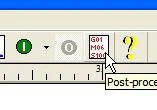
In the window that opens, we select the Post Processor to be used for the milling machine. The post processor outputs the GCODE in the format required by a specific machine.
Since our GCODE will be interpreted and executed by Mach3, we select the Mach3 post processor.
>
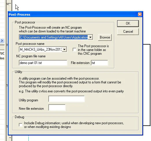
In this window you can also specify the file extension to be used on the GCODE file. The default is .cnc, but Mach3 expects a .txt suffix, so I set the file extension to “.
txt”. Click OK and the GCODE file “demo part 01.txt” is created.
>
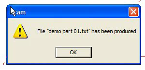
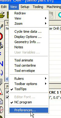
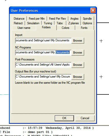
But where? The directory in which the file is created is defined in the View / Preferences / Folders tab, in the NC-Programs dialog box and apparently defaults to the My Documents folder.
Where you actually want the file depends on the relationship between the computer on which you are using Dolphin (which we’ll call the CAD PC) and the controller that runs your CNC mill (which we’ll call the CNC PC.)
One option is to use a flash drive to move the files between systems. On ancient non-PC controllers, your only option may be to use a floppy disk or a serial-port interface.
Luckily, Dolphin supports a serial communications protocol just for such situations.
In my case, both the CAD PC and the CNC PC are Dell X300 laptops located in my shop. Both PCs are in a Windows XP Workgroup on a WiFi network. So, using Windows XP, I set up shared folders on both computers.
I create a folder in My Documents named CAM Code and set that directory as the output directory for CAM code.
After the GCODE file is output, I copy it from the CAM Code folder on the CAD PC to a networked folder, named FH CAM Code that I created on the CNC PC.
In Mach3, I simply load the GCODE file from that directory and I’m good to go.
I tried specifying the networked folder on the Mach3 laptop as the output folder in Dolphin CAM, but that didn’t work, so it looks like I’m stuck with the extra copy step.
Another possibility, that I haven’t tried yet, is to see if Mach3 can load the GCODE directly from the networked folder on the CAD / CAM laptop.
At other times, I have run Dolphin CAD / CAM on the same laptop that I use as the Mach3 controller: the CNC PC is also the CAD PC. That works fine, but the CNC PC is on a roll-around stand and is too high to sit at to do work for long periods of time.
Over the years, I bought several Dell X300 laptops (cheap) on eBay, so I have the luxury of using them to make my life more comfortable.
Heck, with used XP systems being thrown away in droves, you probably can find a few for free! Am I worried about the FINAL AND CHAOTIC DEATH OF WINDOWS XP? A little, but I’ll deal with that later.
All of my critical stuff is backed up on multiple drives. I use Laplink Diskimage to save complete disk images which I can restore as needed to revert to a known state.
Check it out - it’s a great program and not very expensive.
But what about the malware that will enter my network through unsupported XP and eat the files on my Windows 8 computers? I’m hoping that my firewall, and careful usage protocols, will protect me against that.
I guess I could set up a separate network, not connected to the internet, for my XP computers if I get worried. Life was much simpler with DOS (or CP/M, anyone?)
>
Making a Test Run
Having transferred the GCODE file to the Mach3 controller PC, we can now get down to the actual cutting of material. We’ll make our part out of 1/4" thick aluminum plate, but first we’ll do some test cuts using stiff foam insulation board.
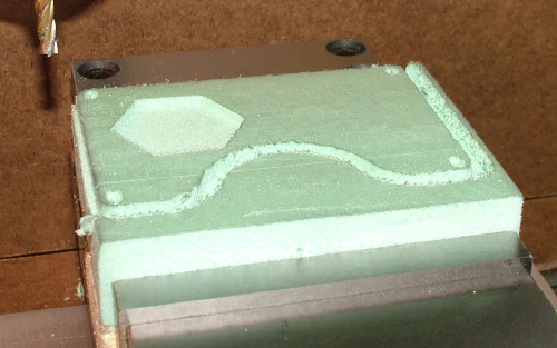
Especially when you’re first learning CNC, and are likely to make some mistakes, it’s a good idea to do a test cut of the part using some soft and inexpensive material such as wood or foam that is relatively easy to cut and less likely to damage a cutting tool if something goes wrong.
For my testing, I’ve been using green foam insulation board, available from Lowes or Home Depot in 4x8’ sheets. It is available in 3/4" and 1" thicknesses at my local Home Depot.
I haven’t checked, but it may be available in greater thicknesses from other sources.
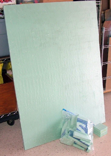
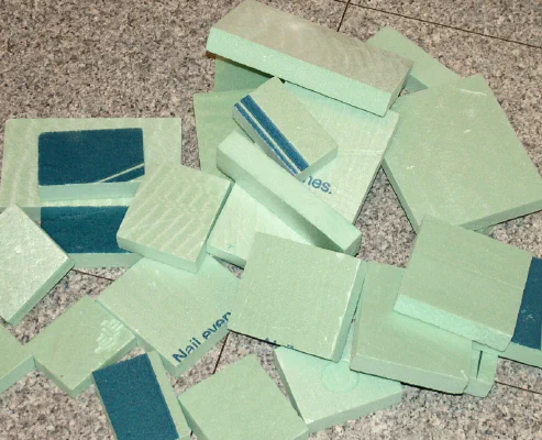
I cut it down on the radial arm saw to small blocks that are a convenient size for working on the KX3 mill: 2x3, 3x4, 4x5 and 5x7 inches, for example.
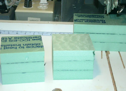
For experimenting with thicker workpieces, I cut several larger pieces, say 10x13", stack them in two or three layers, and glue the layers together using white glue.
After the glue sets for a few hours, I cut the blocks down to 3x3x3" or whatever size I need using the radial arm saw. I used a few blocks made this way when I was working out the machining operations for the Mah Jong money stick holders shown earlier in this article.
One drawback to the foam is that it produces a lot of small, statically charged particles when it is cut. It’s not as messy as sawdust, and the static tends to make it stick to things nearby the milling area, so it doesn’t spread around the shop too much, but you should keep a vacuum cleaner close at hand to clean up the stray bits after a test run.
Another disadvantage is that it will not show fine details in the work; it’s useful only for getting a rough draft of the machined workpiece. For more detailed prototypes, there’s a machinable wax designed for this purpose, but it’s quite a lot more expensive than the foam and not available locally.
If you have more time than money, you can make your own machinable wax. I haven’t tried this, but it looks interesting. If you keep the chips reasonably clean, you can melt them down and reuse them.
For the initial test runs, rather than using an end mill or drill bit in the chuck, I use a length of acetal plastic rod, 1/4", 3/8" or 1/2" in diameter and about 2-3" long to simulate the cutting tool.
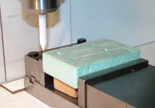
Acetal is relatively inexpensive, readily available, can easily be machined to a dull point in a lathe and is flexible enough to prevent damage to the mill or vise if something goes wrong.
If the drilling operation runs amuck, as sometimes happens while we’re learning, the simulated tool will do much less damage and is less costly to replace than an actual cutting tool.
Here’s a short video showing the acetal “drill bit” drilling holes into a 2x3" foam block.
More than once, I’ve been surprised during the test of a drilling operation, when the fake tool plunged much more deeply than I had planned, and was pushed back into the drill chuck as the tip of the “tool” hit the bottom of the milling vise.
Had a real drill bit been used, the consequences would have been much worse. For this reason, I set a relatively low Z-axis drive rate in the Motor Tuning section of Mach3, to give me extra time to react.
As I gain more experience and confidence, I can ramp up the motor speed.
With the acetal “drill bit” locked in the chuck, I zero the tool visually to the back, left and top surfaces of the workpiece. When testing with this dummy tool, the zero does not need to be precise, so visual alignment is good enough.
My last trick for staying out of trouble is too keep the spindle well above the top surface of the work during the initial test run. That way, as the program runs through its stages, I can verify that the tool is moving where it should, with minimal risk.
Although the dummy tool will “drill” into the foam, it can’t cut to the sides like an end mill. Therefore, I make a final test run with the acetal probe just above the top surface of the workpiece to make sure that the real cutting tool will go where it is expected to go.
After that’s confirmed, I replace the acetal probe with a real drill bit or end mill, zeroed to the top surface of the foam, to do further test cuts to make sure that all of the cutting operations go smoothly.
With that completed to my satisfaction, I replace the foam with the actual workpiece.
Preparing the Raw Material
I’m a little overzealous about not wasting raw material. Considering my near-zero income now that I’m retired, I don’t have much money to spend on raw material, but my time is relatively cheap.
Therefore, rather than wasting a piece of new material, when milling a one-off part, I first search through my bins of scrap for a suitable piece of material, about the right size and shape for the part I want to make.
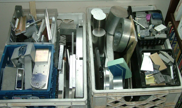
Ideally I find a piece of scrap a little bit larger in each dimension than the part I want to make. Then I mark out the finished size using a surface plate, height gage and layout dye, or using the carriage controls and DROs in Mach3 on the mill, I cut the part down to its finished exterior dimensions.
I’ve found that I can manually control the CNC mill just as effectively as a manual mill for trimming a piece of stock to size before beginning the automated CNC operations.
I set up the workpiece in the vise just as I would in the manual mill, then set the spindle speed in Mach3 and use the X, Y and Z jog controls to do the actual cutting, while monitoring the Mach3 DROs to cut to the desired dimensions.
I don’t know whether or not this is considered a standard practice, but it seems to me to be safe and effective.
While watching experienced CNC users on YouTube videos, I noticed that they will often use a piece of stock that’s slightly oversize in the X and Y dimensions, and cut the part out from it by milling along the outline of the part (preferably as the final operation ;-) This leaves a hollow shell of scrap material still held in the vise while the part is cut free.
An advantage of that approach is that it is not necessary to take time to mill the workpiece to size or even to zero the mill to the edges of the workpiece; the part will come out the right size and square, even if the rough stock was not square to the vise or to the table.
Which method you use is up to you. The first method wastes less material, the second method wastes less time. The choice is yours to make.
>

For our current example, I’ll use a piece of raw stock already cut and milled to 2.00 x 3.00 inches. Therefore, it will not be necessary to make a final CNC milling pass around the outside perimeter of the workpiece.
Setting the Zero Point
With our 2x3" aluminum stock in hand, the next issue is where and how to zero the CNC machine to the workpiece. If you’ve operated a manual mill before, you no doubt know that dimensions are easiest to work out if they are referenced to an edge or corner of the workpiece (assuming a rectangular workpiece that has corners).
For a circular workpiece, the center may be the most logical zero point. Clearly, the choice of the zero point is not absolute: it can depend on the shape of the workpiece, key features and the type of operations to be performed.
For the simple rectangular part that were making now, one of the corners makes a good reference point. Usually, I choose the back left corner as the zero point. First I use a mechanical edge finder to locate the the fixed jaw of the milling vise to establish Y zero. That way, as long as I don’t move the vise on the table, the Y zero stays the same from job to job.
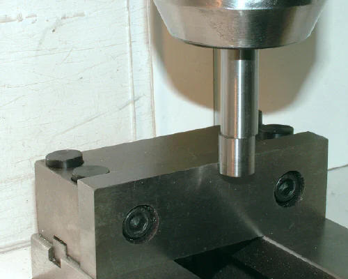
For the X zero, I touch off the edge finder against the left edge of the workpiece. Since the edge finder I used is 0.500" diameter, I set the X-axis DRO to -.250 in Mach3. Usually, I have an adjustable X-axis stop attached to the vise, and zero to the stop, but this is a new vise for which I haven’t yet made a stop.
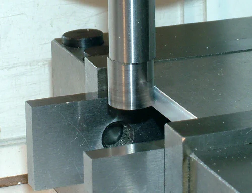
For the Z zero, with the appropriate cutting tool installed in a collet or chuck, I lower the spindle until the tip of the cutting tool just touches the surface of the workpiece, then zero the Z axis DRO in Mach3.
On a manual mill, you can use the quill feed and feel when the tool just touches the surface of the workpiece, but the KX3 has no quill, so there’s no tactile feedback.
Experienced mill users recommend using a thin slip of paper or foil as a shim between the tip of the cutting tool and the top surface of the workpiece.
The spindle (while stopped!) is lowered slowly until the tip of the cutting tool just starts to grab the slip of material, then the Z-axis DRO is set to the previously measured thickness of the shim material.
That method prevents the sharp edges of the cutting tool from marring the surface of the workpiece and is more accurate than trying to judge by eye when the tool touches the surface of the workpiece.
In this example, all we’re going to do is drill four holes through the workpiece, so setting the Z-axis zero is not at all critical. As long as the tip of the drill bit is zeroed to within about 1/8" of the surface of the workpiece, that will be close enough.
Just pick any spot on the surface of the workpiece, lower the tool and set the Mach3 Z-axis DRO to zero.
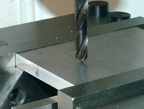
In our current example, only one tool will be used. In a more typical milling job, several tools would be used. As Mach3 executes the GCODE instructions, it will pause and request a tool change when one is required.
At that point, you manually raise the head to provide clearance, remove the current tool, install the new tool and zero the Z-axis for the new tool to the surface of the workpiece.
Of course, if you happen to have a CNC mill with an automatic tool changer and tool holders that let you pre-set the tool length, Dolphin CAM can use those features so that every tool change happens automatically during the sequence of machining operations.
Machining the Plate
Now, our workpiece in the vise, the drill bit installed and the X, Y and Z zero points established, we’re ready to begin cutting metal. Click on the Cycle Start button on the Mach3 screen to begin machining.
>
If you’re changing tools manually, the program normally will pause at this point, requesting that you install the first tool. If you already have installed and zeroed the tool to the surface of the workpiece, just click on Cycle Start again.
(Note: If you have already installed the tool, you can skip this paragraph.) You may need to raise the spindle to make room to install the tool. If so, use the PgUp key on the Mach3 controller PC, but be careful not to touch the arrow keys that move the X and Y axes.
After installing the tool securely in the collet or chuck, lower the Z-axis and zero the tip of the tool to the surface of the workpiece as described above. Be sure to reset the Z-axis DRO to zero, if the tool is touching the workpiece, or to the shim thickness, if you used a shim for zeroing. With the tip of the tool now zeroed to the workpiece, click on the Cycle Start button to resume machining.
At this point, Mach3 should execute the GCODE, performing all of the cutting operations up until the next tool change. When all of the operations for the first tool are completed, Mach3 will pause and again request a tool change.
Install the new tool following the same procedure you used for the first tool, then click on Cycle Start to resume machining. Since our example uses only a single tool, the 1/4" drill bit, the GCODE should run to completion after the initial Cycle Start.
In case you missed it at the beginning of this article, here’s a short video showing the drilling operation.
Conclusion
Well, that pretty much wraps up our exercise. I hope you found it informative and helpful in your pursuit of CNC knowledge.
If you had trouble, don’t be discouraged; learning this stuff takes time and repetition. Believe me, I know!
If necessary, start at the beginning and work through all the steps again. If you have trouble at a particular spot in the CAD/CAM operations, try working around the problem using a different approach.
Although I’ve tried to document all of the steps accurately, it’s possible that I’ve missed something, or explained it in a way that’s not very clear.
At this point you may be thinking: “Well, that was interesting, but it sure was a lot of work just to drill four holes.” But, remember, the real payoff for using CNC comes when you’re making more complex items - and multiple copies of them.
I deliberately made this example about as simple as it could get, hoping to make it as easy as possible for beginning CNC enthusiasts to have a successful first encounter with automated machining.
Since just about everyone has experience drilling holes, it’s easy to relate what’s happening to what you already know. Also, there’s less that can go wrong with a drilling operation, since the mill is moving only one axis at a time.
And, if you should happen to destroy the drill bit, it’s a lot cheaper to replace than an end mill ;-)
Through this exercise, we’ve covered the basics of CAD, CAM, GCODE and CNC machining. We’ve also learned some of the terminology and learned how the various elements of CNC machining work together.
Of course, there’s tons more to learn, but I’m confident that this foundation will help you along the way.
I hope to follow up this article with one or more additional exercises that cover other aspects of CNC machining. Until then, keep makin’ chips!