C6 Lathe Enhancements
After more than ten years working with several versions of the C2 mini lathe, the C4 mid-size lathe and the C6 lathe, I found that I was using the C6 with increasing frequency. I’ve previously documented the standard features of the Sieg C6 lathe, if you’d like to learn more about it.
In this page, I’m going to describe a number of enhancements I’ve made to the C6 lathe. See below for an index to sections.
To make it easier to keep track of which sections of this page recently have been updated, I’m going to maintain the index below in chronological order, with the sections most recently updated at the top.
This may make the index seem confusingly organized, but should help readers to quickly determine if there’s anything new to read since their last visit.
- DRO for the X Axis (05/20/12)
- Remote Digital Readout (RDR) for X and Z axes (04/29/12)
- Variable Speed Power Feed (04/29/12)
- 6" 4-Jaw Chuck (04/28/12)
- Other Minor Upgrades (04/28/12)
- Big Chip Shield (BCS) (4/24)
- Gear Storage (4/26)
- Thread Pitch Gear Chart (4/26)
- Cross Slide Thumb Screws (4/28)
- Variable Speed Spindle Drive (04/03/12)
- Variable Speed Power Cross-Feed (04/03/12)
- 6" 3-Jaw Chuck (04/03/12)
- 8" 4-Jaw Chuck (04/03/12)
- DRO for the Z Axis (04/03/12)
- Digital Readout (DRO) for the Tailstock (04/03/12)
Here are some other C6 mods I made soon after I got the C6. They are in the C6 review article.
These upgrades have made a good lathe into a great lathe. Since this is an ongoing project, I’m going to update this page periodically, adding more new information on each pass, so check back from time to time if you’re interested.
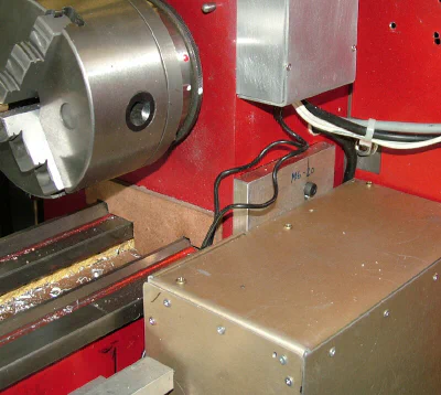
Variable Speed Spindle Drive
 Speed control for variable speed motor drive
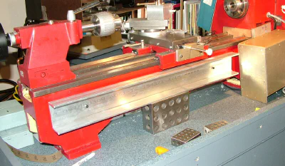
The C6 is a well-made lathe with many good features, but it uses a traditional drive arrangement with an AC induction motor coupled to the spindle by belts and pulleys.
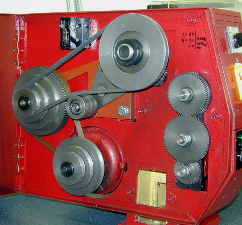 Standard C6 drive train
Once you become accustomed to variable speed drive, as on the minilathe, it’s hard to live without it. To change the spindle speed, you have to shut off the lathe, loosen the belts, move them to another set of pulleys, tighten the belts and restart the lathe.
But aside from that, I really like the comparatively “wide open spaces” and larger work capacity of the C6 compared to the mini lathe and the C4.
Note: there are two variable speed versions of the C6 manufactured by Sieg, the C6B and the SC6, but as far as I know, they never have been sold in the U.S. I’m not sure why, since they’re popular in Europe, Australia and New Zealand.
Some years ago, after seeing Steve Bedair’s variable speed modification for the Harbor Freight 9x20 lathe, I decided to convert the C6 to variable speed. I noticed a discarded exercise treadmill put out for trash pickup in our neighborhood and asked the homeowner if I could take it away. The lady of the house kindly assented, but warned me that the treadmill did not work. No problem, right?
Some testing quickly showed that the motor worked fine. The problem, whatever it was, was in the motor controller electronics. I have a basic knowledge of electronic troubleshooting, but finding the problem and fixing it seemed like it could take a long time.
I decided to take the quick route to success and bid on some eBay auctions for a controller just like the one that Steve had used for his conversion. I won one of the auctions and was ready to get started on the conversion to variable speed.
The C6 project, however, was destined to be postponed. Demands at work and other responsibilities conspired to keep it on the back burner; and there it stayed until a few months ago.
Now, I’m retired and have a lot more time to devote to shop projects, so it seemed like a good time to get back to work on the C6.
The variable speed motor conversion was pretty quick and easy. Within two weeks, I had the motor in place and working. It took another few weeks to make a sheet metal enclosure for the motor and protective guards for the left end of the lathe where the belts, pulleys and gears are turning.
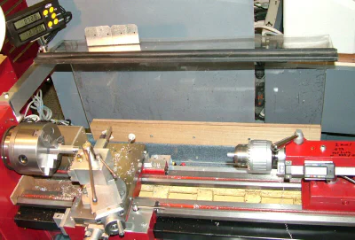
Here’s a few photos of the lathe in its current configuration:
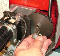
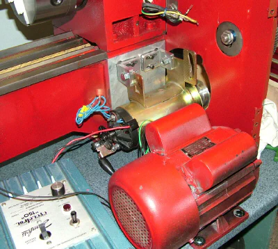 Old and new motor shown together
Even though the new motor is quite a bit smaller than the stock motor it has just as much power, if not more. Plenty at least, for anything I have needed to do.
It has a higher top speed, which is reduced by the belts and pulleys to provide a lot of torque.
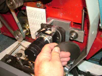
I had to make a support plate and some custom brackets to mount the treadmill motor where the AC motor used to go.
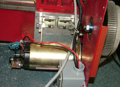 Treadmill motor in place
I made a protective cover out of some gold-colored sheet aluminum that I salvaged from a discarded obsolete robotic computer backup tape drive. I don’t have any real sheet metal tools such as a shear or bending brake, so I had to improvise using the bandsaw and shop vise.
That considered, it didn’t turn out too badly.
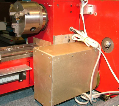 Variable-speed motor with cover in place
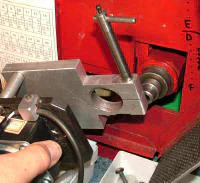
After I removed the stock motor controls for the AC motor, the sloping front panel of the headstock was just right for mounting the motor speed controller that I won on an eBay auction.
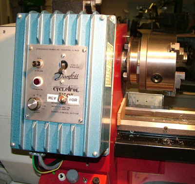 Motor speed control
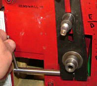
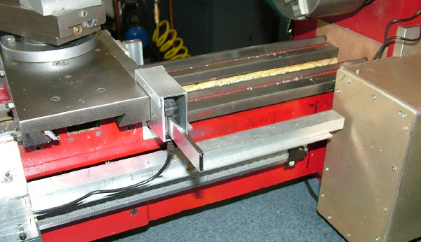
The new DC variable speed motor was too fast to couple directly to the spindle pulley, so I kept the original idler pulley and belt in place. This turned out to be useful: I keep the belt on the high range pulley for most operations but can switch it to a lower range if I really need a lot of torque at lower speeds.
It stays in the high range 95% of the time which, with the variable speed motor, gives me a wide range of speeds with excellent torque. In the lower right area, you can see the gear motor for the variable speed power feed.
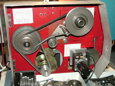 Belt and pulley drive
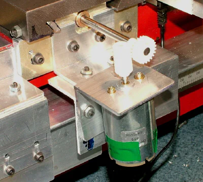
Variable Speed Power Feed
The variable speed power feed is really nice to use. Unlike when driving the leadscrew from the spindle, with this arrangement you can adjust the feed speed on the fly to match what you’re doing.
It’s great for reducing chatter by changing the speed, and for slowing the speed down to make final finishing cuts. It stays on the lathe at all times except when I need to cut threads (see below).
In the current incarnation, the motor and speed controller I’m using came from a Sieg power feed for the mini mill. It works well, but still needs some tweaking before I’m completely satisfied with it. I may end up using a different motor and/or gear train before I declare it done.
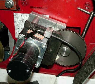 Power feed drive motor and gears
The speed control sits down below the speed controller for the main spindle motor. I made the plastic box using my plastic bending fixture, then spray painted the inside red. This leaves a shiny surface finish from the acrylic plastic.
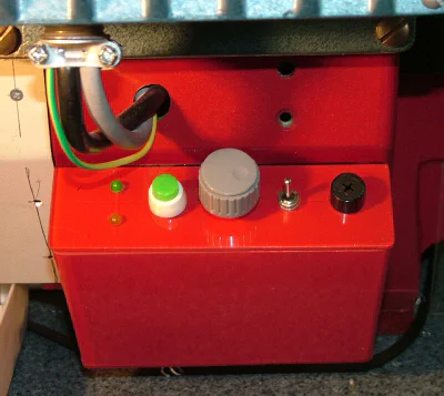 Power feed speed controller
I do most of my thread cutting using taps and dies - it’s faster and more convenient than single point thread cutting - but there are situations where single point threading is called for:
- threads for which a tap or die is not on hand
- large threads, such as on a camera filter, for which a die is not available
- threads on shafts that are not standard bolt diameters
- fine threads, such as on a microscope eyepiece
- threads that must be as concentric as possible with the center of the workpiece
- starting threads on larger diameter rods (> 3/8" dia.) that are difficult to cut with a die
There probably are other situations, but those are the ones that come to mind at the moment.
Changing from the power feed to the gear train takes less than a minute:
- Unscrew the gear retaining thumb screw
- Remove 90-tooth gear
- Loosen locking lever
- Remove motor drive assembly
- Place gear frame on leadscrew bushing
- Lock gear frame in place with lever
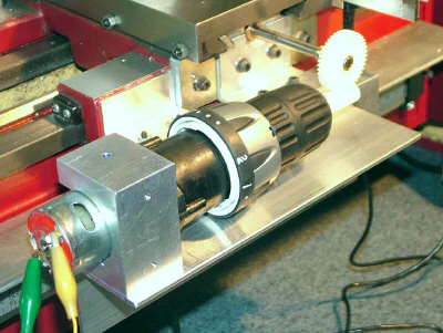
Variable Speed Power Cross-Feed
Many of the lathes made in the U.S. from the 30’s through the 60’s had power cross-feed as a standard feature, but you don’t often see it on the low-cost lathes (under $1000) made today.
That makes sense, since its a feature that you can live without on a lathe with a 7" or 9" swing. However, if you’ve ever tried to face a disk 4" in diameter or larger, you can appreciate the value of having one.
This was brought to my attention most recently when I purchased a low-cost belt-disk sander (BDS) from Harbor Freight (HF). I have a nice older BDS made by Delta, and I use it often for cleaning up sharp edges on milled work and for many other tasks.
Over the last year or two, I’ve found myself doing more and more wood work - mainly to make benches for the shop - and it turns out that the BDS is very handy for smoothing the edges on woodwork (who woulda thought?).
And, when you use it for wood, it produces a lot of sawdust. So it was, that the BDS was moved from its long-standing place of honor in the metal shop to a new spot in the woodworking area in the garage.
It made sense to keep it there, right next to the shop vac, which can attach to it via a dust port.
Anyway, I soon missed having the BDS in the shop near the mill, so I decided to buy a new one on sale (of course) at HF. Its not as nicely made as the old one, using sheet metal where the Delta uses castings, but I determined that it would be good enough for its intended use.
While assembling it, I was a bit dismayed by the rough surface and spiral grooves on the disk sander back plate. It looked like it had been faced on a lathe using a chunk of stone as the cutting tool.
Naturally, I had to fix that.
I mounted the plate in the chuck on the C6 and began the facing process, but with each pass over the face, I experienced chatter and that left a pattern on the face nearly as bad as the one I was trying to fix.
Even after fooling with various speeds and feeds, and putting a backing pad behind the plate, I still couldn’t get a nice finish. To make matters worse, facing a 6" disk at low feeds and speeds is a slow and tiresome process, and it’s hard to maintain an even feed across the face.
That’s when I decided that I needed power cross-feed.
The Sieg C4 has power cross-feed and I had gotten excellent results on some similar jobs when using it. However, after I upgraded the C6 to variable speed drive, I decided to sell the C4 to free up some badly needed bench-top space.
The C6 will do nearly anything that the C4 will do - anything except power cross-feed.
I’m still working on this project, so stay tuned… Meanwhile here’s a few photos of various configurations I’ve tried.
I salvaged the motor and some other parts from a low-cost 9.6V drill from HF. I bought the drill for this purpose a few years ago, but just now got around to using it.
As with most of this project, I made up a bunch of brackets with slots from standard aluminum “L” stock. This material provides a lot of flexibility to connect things together while prototyping.
 Early trial using drill motor and worm gear
Another later configuration using a different cannibalized drill.
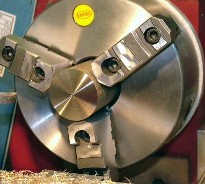
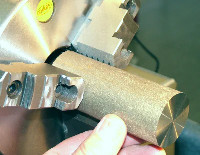
6-Inch 3-Jaw Chuck
The stock 5" chuck is good for routine work, but really doesn’t take full advantage of the capacity of the C6.
 6-inch, 3-jaw chuck
I purchased the 6" 3-jaw chuck from Shars and made a backplate from some scrap aluminum plate. I’ve been using the chuck for a few weeks, but still need to trim down the diameter of the backplate to match the lathe. Later.
This is the first chuck I’ve owned that has 2-piece jaws. The front faces of the jaws can be removed and replaced with custom jaws made from aluminum or pretty much any other material, depending on the intended use.
I found some examples on the internet where this type of chuck was used with custom-made jaws to hold aluminum car wheels for turning and facing. Obviously, it was a bigger lathe than the C6, but the possibilities got me thinking (always a dangerous thing!)
What surprised me when I got the chuck was the large size of the center hole. At about 1-3/4" diameter by 4-1/4" deep (including the jaws) I can hold much bigger work than on the stock chuck. I think I can gain another 1/2" of depth if I bore out the back plate to the same diameter as the center hole in the chuck. In the photos below, I’m facing a piece of rough brass stock 1.675" in diameter by 4.125" long.
 Facing brass rod over 1.5" in diameter
The depth of this chuck makes it possible to handle some stock that would otherwise be too large; certainly outside the limits of the stock 5" chuck.
6" 4-Jaw Chuck
I bought this chuck from JTS machinery. I already had the monster 8" 4-jaw, which is great for when its needed, but somewhat heavy and oversize for routine 4-jaw work on the C6.
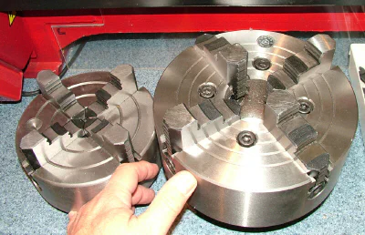 The 6" 4-jaw with its bigger brother, the 8" 4-jaw
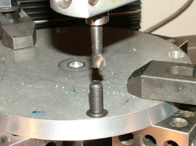
Finally got the back plate finished, so now I can use this chuck. It was made from a scrap piece of 1/2" thick aluminum plate. The extra hole below the left stud was already in the plate from some former life.
Not thinking ahead, I drilled the holes for mounting the chuck to the backplate before boring the spindle recess. I drilled them on the SX4 mill after centering on the temporary center hole that was used to hold the back plate in the 3-jaw chuck in order to turn down the circumference after rough-cutting the circle in the bandsaw.
All of the drilled holes should have been drilled after boring the recess for the lathe spindle, and referenced to the center of the spindle bore.
 Drilling the chuck mounting holes
So the result, in this case, is that the chuck is a little bit off center; only about .012", but enough to be visible when its rotating. Fortunately, this is a 4-jaw chuck so any work held in it will get centered properly when installed in the chuck.
The only downside, then, other than shame, is that the chuck will be a little bit out of balance at high rpms. I’m not worried about that since I nearly always use the 4-jaw at slower speeds because the workpiece often is not symmetrical.
In any case, it’s not a big deal to drill a new set of mounting holes that are properly centered, so I’ll probably do that before long.
After drilling the holes through the back plate, I used a boring head and boring tool to counterbore the holes to recess the bolt heads.
 Testing the bolt head fit in the counterbored hole
Next I bored the spindle recess by mounting the back plate on a faceplate. As mentioned above, I should have done this step before drilling the chuck mounting holes.
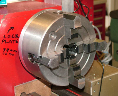
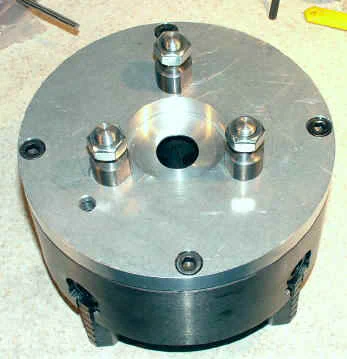
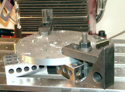
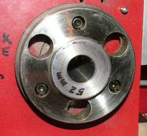
The C6 spindle has a chuck mounting system that I have not seen on any other lathe and that I suspect is unique to this model. Each chuck backplate (and the faceplate) has a set of three studs, threaded on both ends.
One set of threads holds the studs on the backplate; the other set of threads hold the nuts that lock the chuck to the lathe spindle plate.
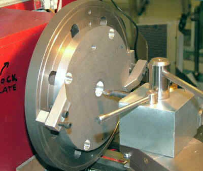
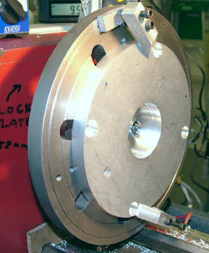
Just behind the spindle is a steel locking plate, about 3/16" (5mm) thick, that has 3 keyhole shaped slots cut along an arc. The keyhole slots line up with holes through the spindle plate.
When mounting a chuck, the back plate studs pass through the large part of the keyhole and the plate is then rotated about 15 degrees so that the narrow part of the keyhole is positioned over the stud thread.
In this position, the nuts on the studs can’t pass through the narrow part of the keyhole, so that the chuck is held safely in place while the nuts are tightened.
This feature gives me a lot of comfort when mounting the relatively heavy 6" and 8" chucks.
 Slots open
 Slots closed
To make it even more foolproof, I added some red and white nail polish dots. When the white dots are aligned, the plate is in the “safe” (closed) position; when the white dots lines up with the red dots, the plate is in the “unsafe” (open) position.
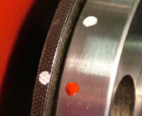 “Unsafe”
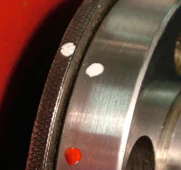 “Safe”
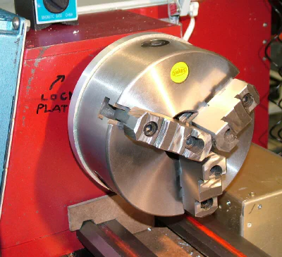
8" 4-Jaw Chuck
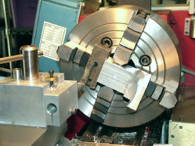 8-inch 4-jaw chuck in action
Safety Note: the 8" chuck is oversize for this lathe. I bought it with that fact clearly in mind. Due to its large size and mass it is used only as a convenient way to hold large work running at low speeds (e.g 400 RPM or less)
I actually bought this chuck several years ago. It’s been great for a number of jobs that would have been too big for any of the other chucks.
Remote Digital Readout (RDR) for X and Z Axes
The X and Z axis DROs connect to a common 2-axis Remote Digital Readout (RDR). The two rules, 6" and 20", and the RDR are sold by Shars Tool as a kit, part # 303-9246. I selected that particular kit after measuring the C6 to determine what length rules were needed. A range of different rule lengths is available to fit various sizes of lathes.
Shars also sells a similar range of 2 and 3 axis “glass sensor” DRO systems, like the ones I used on the SX4 mill. They’re more precise and more versatile, but cost a lot more than the capacitive type sensors used on this unit. But, hey, if you’ve got the money, go for it!.
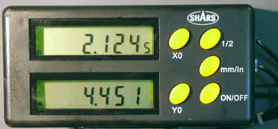
The display uses LCD technology with sharp, black numerals on a light-green background. Backlit by LEDs, the numerals are about 1/2" (13mm) tall and are easily readable from several feet away in a wide range of lighting conditions.
The front of the display is a shiny clear material. It looks like glass, but I don’t think that it is glass. The two DROs have telephone-style clip connectors on the RDR-end, that plug into the right side above the power cable.
Operation couldn’t be much simpler; the controls are as follows:
- X0 - zero the X axis display
- Y0 - zero the Y axis display (which in this application is the long Z-axis of the lathe)
- 1/2 - toggles X-axis display between full units (diameter) and 1/2 units (radius); see below
- mm/in - toggles between mm or inches as the units to display
- ON/OFF - turn the display unit or or off.
Readings are maintained even if carriage or cross-slide is moved when RDR is off.
The 1/2 units feature is a great convenience. As you know, when turning a workpiece, the diameter is reduced by twice the depth of the cut. So, for example, if you wanted to reduce the diameter of the workpiece by 0.200", you would advance the cross-slide by only 0.100".
In 1/2 mode, the RDR does the compensation for you: to remove 0.200", press the X0 button to zero the display, then advance the cross-slide until the RDR upper window reads 0.200". Easy and less error-prone.
Six powerful neodymium magnets (the ones that look like silver buttons) are built into the inside back panel of the RDR so that it can easily be attached to any convenient ferrous metal surface.
Initially, I just glued some galvanized hardware L-brackets to the top lip of my giant chip shield to hold the RDR.
While I was working out the placement of the DROs, I clamped the RDR temporarily to the metal back of the drive housing.
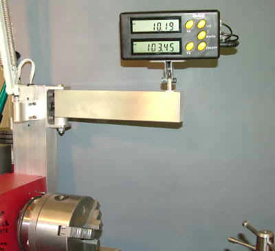
RDR Arm
Depending on the location of light sources, such as windows, overhead lights and shop lamps, reflections from the surface could be problematic, so I decided to make an adjustable arm to mount the RDR.
It needs to be mounted where it has good visibility but is out of range of any chips and fluids that may come flying from the chuck area. At the same time, it needs to be within easy reach, to operate the push-button controls, so I decided to make a swivel-arm to support it.
 RDR mounted on shop-made arm
It should be evident that the lathe operator should not reach over the spinning chuck to operate the RDR buttons, but there’s no reason to do so, since the buttons normally would be used only when the lathe is stopped while the workpiece is being set up.
I think I’m going to move it up higher, to get it farther away from the chuck and to clear the chip guard that was removed when I was doing the RDR installation.
The arm can be rotated around the bolt at the left end of the arm, swinging it completely out of the way if that is ever necessary. The RDR support bracket swivels and tilts.
I made the bracket from 3 standard hardware galvanized L brackets cut to shape and soldered together. While the magnets in the RDR hold it tightly to the bracket, I screwed two #4 sheet metal screws into the back of the RDR so that it could not be knocked loose and fall into the work area.
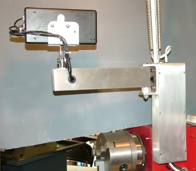
RDR Arm Update
Naturally, like everything else in my shop, the C6 bench is on wheels, so it’s easy to move it out where I can work on the back side. The big chip shield just lifts off and is stored out of the way while I’m working on the back of the lathe.
When I replaced the chip shield after installing the RDR arm, I could see that it was going to be in the way of moving the arm back. I was also concerned that the RDR was too close to the chuck for good protection from chips, oil, cutting fluid, etc.
, so I decided to move the RDR arm up about six inches higher.
I used a 10" length of the heavy C channel that I had originally intended to use as a protective shield for the long Z-axis DRO. Since nothing’s ever simple, the new arrangement was in the way of the swing-arm lamp, so I decided to mount the lamp support on the front of the upright.
That actually worked out well - the lamp can be swung around to provide light to the back side of the lathe if I’m working there, or to the gears and drive train. The RDR now is well away from the chuck, so the push buttons can safely be operated when the chuck is rotating (but it’s still safer to stop the chuck first.)
 A view of the back of the RDR support arm
I made a back cover for the upright out of some scrap aluminum sheet. The RDR power supply and some of the cables for the RDR are conveniently stored in the upright channel and the lamp cable is routed through it.
Rubber grommets protect the cables where they enter the aluminum channel.
 A closer look at the lamp and arm supports.
I made some thin washers from 1" dia. Delrin. They sit just above and below the rotating end of the arm to provide a low friction bearing surface. A thick washer cut from 1" dia. aluminum fills the gap between the rotating arm and the bottom of the support bracket.
With the washers in place, the arm rotates smoothly but stays firmly in place where you position it. A Nylock-type nut at the bottom is tightened just enough to provide enough friction to keep the arm from moving freely.
Using the X-axis RDR
The most basic way to use the X-axis RDR is to zero it to the OD of the workpiece. Let’s say we measure the workpiece using a digital caliper and it’s 0.742" in diameter and we want to turn it down to 0.700" diameter. We could simply move the cutting tool inward until it touches the surface of the workpiece, then zero the X-axis RDR.
We want to remove 0.042", so we need to advance the cross-slide by 1/2 that amount, or 0.021". Let’s say we advance the cross-slide until the RDR reads 0.018, take a roughing cut, then advance again until the RDR reads 0.021 and take a finishing cut.
That works, with the RDR essentially replacing the linear scale engraved on the cross-slide handwheel dial, but it doesn’t take full advantage of the features of the RDR.
For most of my work when turning, I like the X-axis window of the RDR to display the actual diameter of the workpiece. To do this, first make sure the 1/2 button is in the depressed position.
Next, take a light turning cut to establish a reference diameter. The cut should be just deep enough to get a clean and even surface on the outer diameter of the workpiece.
After finishing the cut, without moving the cross-slide handwheel, stop the lathe, then press the X0 button to zero the X axis display.
Carefully measure the workpiece diameter using a micrometer, digital caliper or dial caliper. Now advance the cross slide until the X-axis display reads exactly what you measured (let’s say it’s 0.742"). When the RDR X-axis display reads -0.742, press the X0 button again to zero the display. If your measurement was accurate, the tip of the cutting tool will now be exactly at the centerline of the lathe.
Retract the cross-slide back until the display reads 0.742 and the tip of the tool will be exactly at the O.D. of the workpiece. From this point on, as you take additional turning cuts, the X-axis readout will display the actual diameter of the workpiece.
If you go through this procedure a number of times, you probably will find that it’s quite challenging consistently to hit the exact diameter that you want, accurate to +/- 0.001". Many variables come into play, such as looseness in the cross-slide gibs, backlash in the cross-slide lead screw, consistency of how the caliper is held, closed and released from the workpiece, etc.
The point is, of course, that even with the precision DRO mounted on your lathe, exact results are not automatically ensured. But there’s no doubt that having the DRO in place makes it easier to reach the goal of exacting work.
And one benefit that I really like is that I can rapidly reduce the diameter of a workpiece towards the target diameter, confident that I won’t overshoot and make the diameter too small.
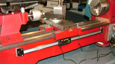
DRO for the Z Axis
A note about lathe axis designations: The long axis of the lathe is referred to as the Z-axis; the cross-feed is the X-axis.
Whenever I turn a shaft with varying diameters on the lathe, I wish I had a DRO on the Z-axis. In the past, I have gotten by with dial indicators, which usually are awkward to fit in the space available, and are limited to a range of 2" at most.
For the C4 lathe, I used a 4" DRO mounted on a magnetic base and clamped to a custom clamp on the carriage to measure Z-axis movement. It worked ok, but, again, was limited in range.
It also was easy, without thinking, to run the carriage back into the magnetic base, thus losing the zero reference point. So this time, I decided to do it right, with a DRO the full length of the Z-axis.
The back of the C6 is pretty wide open, so it seemed like mounting the long DRO would be fairly easy - and it was. As in other prototyping projects, I used Quick Grip glue to glue some aluminum spacers onto the bed of the lathe.
After giving the glue an hour or so to set, I was ready to begin work.
 Concept #1.0
Recognizing that the DRO, as a precision measuring tool, would need good protection from chips, cutting fluids, oil and the occasional run-away workpiece, I ordered a length of extruded aluminum C-channel.
When I was visualizing the setup, I was thinking of having the closed part of the “C” on top and the open part on the bottom, thus giving maximum protection to the DRO.
However, when the C-channel arrived, I was surprised to find that the base was wider and the sides were shorter than I had expected. This discrepancy, of course, was simply a consequence of my not reading the specs carefully.
Anyway, having it on hand, I decided to try it out…
 Concept #2.0
 Concept #2.4
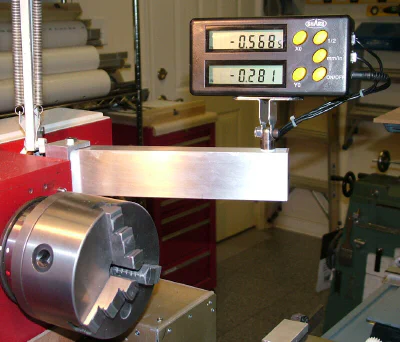
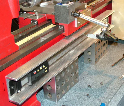
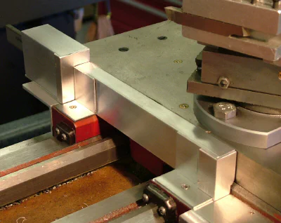
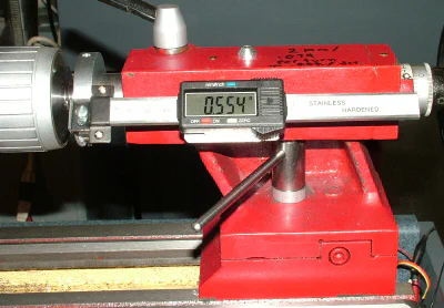
DRO for the X Axis
A note about lathe axis designations: The long axis of the lathe is referred to as the Z-axis; the cross-feed is the X-axis.
I think that most machinists would agree that having a DRO on the cross-slide is more important than having one on the Z-axis or the tailstock. Well, that’s what I thought, anyway, so I tackled the X-axis DRO first.
It was pretty obvious that the back side of the cross-slide would not be a good place for the DRO. It would be in the way of the tailstock, when it’s up close to the saddle for drilling, would block access to the gib screws, and would somehow have to fit without obstructing the carriage lock lever (note: the stock carriage lock is just a hex-head bolt; I added the lever.)
 Concept #1.0
I played around with a vertical-reading DRO, as shown above, thinking that it would be more easily readable than a horizontal-reading DRO.
Looking at the front of the cross slide, it seemed promising, the main concern being possible destructive interference between the DRO and the spinning chuck.
So the goal was to keep the DRO profile as thin as possible, to maximize clearance between it and the chuck. Naturally, the DRO needed good covering for protection from chips, spirals, cutting fluid and the usual hazards around the chuck.
It became clear that a vertical-reading DRO would not be a good choice for the front side of the saddle; however, a horizontal-reading DRO would be impossible to see if covered with the necessary shielding.
Thus I quickly arrived at the conclusion that I’d need some kind of a remote display.
After checking out the usual machinist’s supply houses online, I found a setup at Shars that looked promising. They had several packages intended for use on lathes that included a long DRO for the Z-axis, a short DRO for the X-axis and a remote readout.
I ordered a set that had about the right dimensions for the C6.
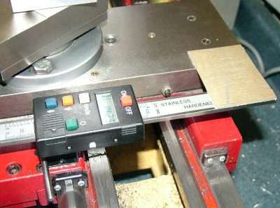
Update 05-20-12
I purchased a DRO kit for the X- and Z-axes from Shars tool, part # 303-9246. The DRO has a nice large-digit display. Seems a shame to cover it up, but there’s not much choice if it’s to be protected. I tried several different mounting arrangements, beginning with the readout positioned between the two H arms of the saddle.
In this location, it seemed to me that there was a lot of risk of the display being hit by the chuck, even with a protective cover over the display. Also, I was not thrilled with the cable dangling down between the ways.
There’s just too much action in that area when the chips are hot and flying, plus the potential for abrasion against the back way. An advantage of this location, though, is that the slide scale is well protected along its full length by the side of the cross-slide.
The slide moves with the cross slide while the readout is fixed to the saddle.
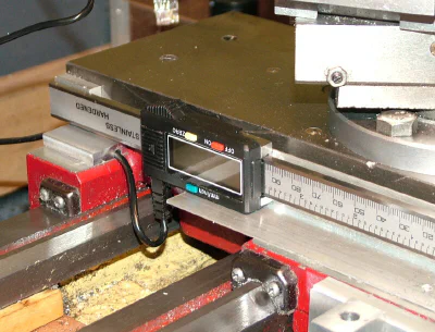
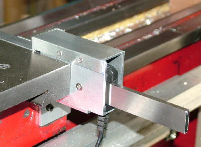
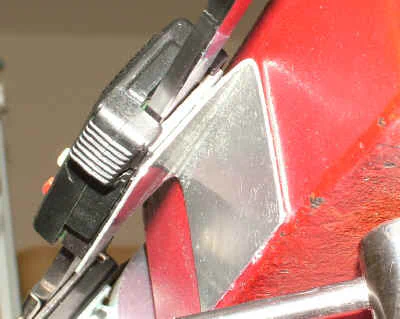
After more experimentation, I decided to mount the DRO with the readout mounted behind the back side of the saddle, supported by a piece of L bracket.
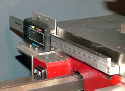
The advantage of that location is that only the DRO slide is between the H arms of the saddle, and, with the protective cover in place, is only 1/2" thick, minimizing the risk of a collision with the chuck and still allowing the saddle to work close up to the headstock.
I made protective covers for the DRO from sections cut from 1x2" thin-wall (1/16") aluminum channel from OnlineMetals.com.
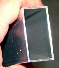 1x2" thin-wall aluminum channel
At the time that I ordered the channel, my plan was to encase the whole DRO in a length of the channel, but I decided instead to cut sections of the channel to fit, to help minimize the profile of the assembly.
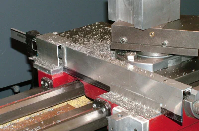
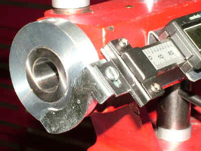
Full-size channel would further restrict how close the carriage could be moved up to the chuck or faceplate. For certain operations, such as facing a thin disk on the faceplate or machining a small workpiece held in the chuck, you want to be able to get the carriage up close.
 Working close to the chuck
By carefully fitting the channel to the DRO, I was able to minimize the amount of room taken up by the assembly. This approach is time-consuming as each piece must be carefully cut to fit with the surrounding pieces.
I used a combination of flat-head screws and Quick-Grip to hold the pieces of the protective shield in place. Screws are used for components that I may need to remove for maintenance and glue is used on pieces that are unlikely to need to be removed.
Here’s how the protective shield looked during one stage of experimentation…
Here again, using QG made it possible to test many configurations without drilling any holes. After a few more days of trial and error (mostly error) the shield started to look better and work effectively to keep chips off of the DRO.
As I became more certain of the locations for some of the parts, I drilled and tapped 4-40 holes and screwed them in place for a more permanent installation.
 Current state-of-the-art DRO shield
A potential disadvantage of this mounting arrangement is that the when the carriage is moved inwards, the DRO scale extends out beyond the back of the saddle.
Since my bench has plenty of extra space behind the lathe, that does not look like it’ll be a problem. Time will tell.
Cable Management
So far I have done nothing to secure the data cable to the DRO; it’s just plugged in and seems to hold well enough for now. My experience with these plugs, though, is that they do not hold very securely, so I’ll probably need to make some kind of cable restraint later on.
I’ve already done that for the long Z-axis DRO.
Protection for the data cables is pretty minimal at this time and more work will be needed in that area. The cables extend loosely down from the support that holds the remote readout and then extend along the protective L bracket that covers the Z-axis DRO.
I definitely need to add some protective covering in the area where the cables run near the chuck. Some C channel, cut to fit, probably will do the job.
The cables are protected for about half their length by running through a section of C channel which, at the moment, is simply glued to the to of the large L bracket over the Z-axis DRO.
At the far end, about 8-10" of the cables must be left loose so that they can move with the carriage. So far, they have held up without any problems, but I’m not real confident that they will operate reliably in this configuration for years at a time.
Here again, I may need to come up with a better solution later on.
Tailstock Digital Readout
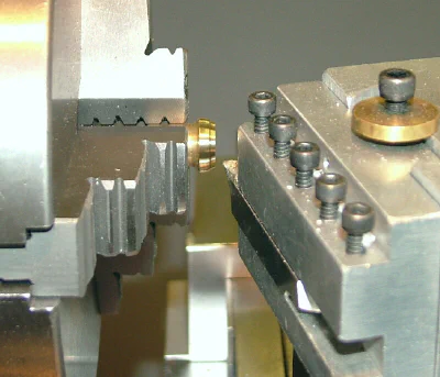
I’m just getting started on this mod. It should be a lot easier than the Y and Z axis DRO installations, though. I needed to get it working to facilitate drilling holes to a specific depth to make an adapter.
The adapter will attach the worm screw shaft for the cross-slide power feed to the threaded drill motor shaft.
The DRO is a 4" horizontal model from Shars Tool. It has extra-large (about 1/2" (1.25 cm) tall) high-contrast digits. When mounted at a convenient angle, its easily readable from several feet away.
Like all of the similar products in this category, it runs for a year or more on a single button battery. It can be zeroed at any point in its travel and can instantly switch between inch and metric units. Since I’ve been doing an increasing amount of work in metric units, it’s nice to be able to use either measurement system without having to resort to a calculator to do conversions.
Before starting in on this, I did a quick Google search to see what others had come up with. The following link (which probably be out of date by the time you try to use it) was to a forum on cnczone.com that had some good ideas and photos.
To get the DRO working quickly, I just knocked out a simple bracket bent from thin aluminum sheet metal and glued it with Quick Grip (QG) to the back of the DRO readout unit and to the tailstock casting.
I turned an aluminum collar to go around the tailstock ram. It’s locked in place by a set screw with a Teflon plug. Another stock hardware L-bracket was cut and filed to fit between the collar and the standard clamp on the end of the DRO rule. The L-bracket (for now, at least) is simply glued to the front of the collar with QG.
 Aluminum sheet-metal bracket glued with QG
 DRO attachment to tailstock ram
I use Quick Grip for all of my prototyping. It sets within a minute or two and lets me quickly position assemblies for testing. However, a few years of use has proven that QG is strong enough to use for permanent or semi-permanent installations without having to lay out and drill holes in the machine castings.
If I ever want to remove or modify a component mounted in this way, the Quick Grip can easily be removed by soaking it with some naptha or acetone (choose your poison!).
Before I’m all done, I probably will make a more elegant bracket to hold the front end of the DRO rule. Not that its necessary - it works fine as it is - but I like the look of machined parts on my mods.
Other Minor Upgrades
Big Chip Shield (BCS)
In a dusty storeroom at a company where I used to work as an IT guy, a plastic cover from a large dot-matrix printer sat idle for years, the printer itself having long since departed.
Then one day, I got notification to clear all of the computer-related items out of the room. We threw out a lot of stuff, but I salvaged the printer cover thinking it might be useful for some future project.
I collect a lot of stuff like this. My wife calls it junk, but she just doesn’t understand…
When I was building the bench for the C6 around 2005, it soon became apparent that the printer cover would make a nice mega-chip-shield. Some years later, I actually got around to mounting it to the bench and it does indeed make a nice chip shield.
Foresight, that’s what I call it. ;-)
Because it’s made from 1/4" thick clear acrylic plastic, it’s hard to photograph, but you can see the black plastic handle that runs along what is now the top front edge.
I glued some galvanized hardware L brackets on top to clamp to the magnetic back of the RDR before I made the RDR arm.
The wood strips along the bottom edge allow the chip shield to slide into place over the back edge of the bench top (the bench top is made from pre-fab kitchen countertop.) I can remove or replace the chip shield in 30 seconds when I need to get access to the back of the C6 for maintenance.
Gear Storage
The treadmill from which I salvaged the drive motor had platforms along each side made from some faux wood laminated panels. I cut a piece of this material, drilled three holes in it and made a platform for storing the change gears when they’re not in use.
I made some Dymo labels showing the gears in each stack. Makes it easy to find and replace gears when setting up for threading. Kinda looks like a Tower of Hanoi puzzle.
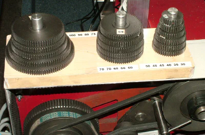
Each gear is labeled with the number of teeth using white Dymo tape, which is much easier to read than the stamped factory markings. To get the Dymo tape to stick, I first cleaned the gear surface with acetone to remove any grease or oil, then put down a layer of clear nail polish slightly larger than the size of the label.
After the nail polished dried, I stuck on the label, then covered it with another layer of clear nail polish to protect the tape.
Whenever I buy nail polish at Wal-Mart, I always buy a few boxes of .357 magnum ammo at the same time. It really makes the cashiers wonder.
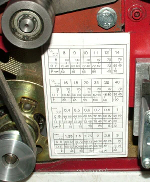
Thread Pitch Gear Chart
I scanned the gear charts from the user manual and made a copy laminated in plastic. The chart is affixed in the gear change area where I can easily refer to it while setting up a gear train for a particular thread pitch.
Cross-Slide Thumb Screws
Unlike the minilathe, the C6 has a ball-bearing race in the cross-feed support. When the cross-slide leadscrew is lined up perfectly with the leadscrew nut, the cross-feed operates smoothly and evenly.
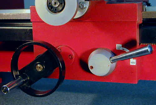
However, if the leadscrew is off-center to the nut, the cross-slide motion can be uneven and jerky. Not only does this make it harder to get a nice finish on a facing cut, I’m pretty sure that it causes undue wear both to the leadscrew and to the nut threads, leading to increased backlash over time.
There is a backlash take-up feature in the nut, but why cause wear unnecessarily?
From the factory, the cross-slide handwheel bearing housing is attached to the cross-slide by a pair of ordinary metric bolts. Assuming that the cross-slide was optimally adjusted at the factory, and did not shift during any bumps and jolts that may have occurred during shipping, you may never need to adjust these bolts.
But if you’re like me, and like to strip the parts down for a thorough cleaning, or want to fool around with adding a cross-slide DRO or power feed, you’ll need to remove and replace these bolts many times.
And it turns out that finding that exact spot where the leadscrew is perfectly aligned with the nut, takes some fiddling each time you tighten the bolts.
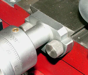
Therefore, I soon replaced the factory bolts with some custom-made bolts with big knurled handles, making them easy to remove, replace and adjust without the need for a wrench.
I haven’t found a foolproof way to achieve perfect alignment automatically, but through much experimentation I’ve gotten pretty good at getting it right by feel.
With the knurled screws, the process usually now takes me less than a minute, compared with several minutes using the original bolts. Someday maybe I’ll figure out an ingenious way to lock in the alignment using stops or something.
Until then, the knurled bolts are a big help.