Grizzly Height Gauge
On this page
There are a few tools in my shop that I use so frequently, and find so indispensable, that I keep a spare on hand. One such tool is a digital caliper; another is a height gauge.
With a spare readily available, work does not come to a standstill if the primary tool is broken, or, I hate to admit, becomes temporarily lost in the clutter of my shop.
Searching fruitlessly for a lost tool quickly makes me grouchy, so having a spare on hand not only keeps the work moving, but helps to maintain my normally positive outlook on life.
A height gauge is used to scribe layout lines on a workpiece at a precise height from a baseline. Most often used for laying out work for milling or drilling operations, the height gauge is also useful for lathe work.
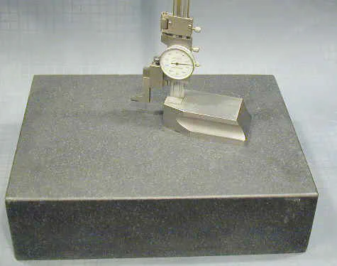
A height gauge must always be used on a very smooth and even base plate - most often a precision-ground surface plate made from granite specifically for this type of work. The surface plate serves as the reference surface for both the height gauge and the object being measured.
Fortunately, good quality, inexpensive, import surface plates are available from many of the usual machine tool suppliers, including Enco, Harbor Freight, MSC, J&L and Grizzly. A good choice for home shop mini-lathe/mini-mill use would be the Grizzly P/N G9449; 9" x 12" x 2" thick.
Pay attention to the shipping weight and charges, though, since even a small surface plate such as this one weighs 25 lbs.
Handled carefully to avoid chipping or gouging the finished surface, a surface plate should last more than a lifetime.
 Height gauge resting on a 9x12x3" granite surface plate
Components of the Height Gauge
The height gauge is fairly simple in construction: much like a dial caliper mounted on a heavy base. The heavy steel base is precision ground on the bottom surface and slides smoothly along the surface plate.
Mounted perpendicular to the base, the vertical column supports a gear rack that engages with a pinion in the back of the indicator dial. As the entire indicator assembly moves up and down the column, the rack and pinion move the dial of the indicator.
Extending from the left side of the dial assembly is a fixed arm on which a sharp carbide-tipped scriber is mounted. The lower surface of the scriber is ground very flat.
When the base of the scriber is flat against the surface plate, the indicator dial can be set to read zero. The front of the dial can be rotated to set the zero point, and then locked in place by a small thumbscrew.
It’s good practice to check to make sure that the indicator is zeroed before making a precision measurement, since the zero point can shift if the height gauge is accidentally knocked over or otherwise jarred.
Naturally, if you treat the surface gauge with the care appropriate for a precision measuring tool, it will serve you well for many years.
In the next section we’ll look at a few common applications for the height gauge.
Applications
There are many ways to use a height gauge, including some, I’m sure, that I have not yet figured out. But the most common use, as the name suggests, is to measure or mark the height of a workpiece.
Let’s take a look at how to apply this for a simple lathe facing operation: facing off a piece of 1" dia. round aluminum stock to a height (length) of 1.00"
The first step is to cut the rough stock with a hacksaw or bandsaw to somewhat longer than the desired finished length. For a finished length of 1.00", I would rough cut the stock to about 1.2 - 1.3".
Next, chuck the workpiece in the lathe, and perform a facing operation on one end. This finished end will become the reference from which the height gauge will measure the finished height of 1.00"
Prepare the workpiece with layout dye. Layout dye is used to provide a high contrast background into which a sharp reference line is scribed by the height gauge.
For either use, the workpiece usually is first prepared by milling or facing at least one face to provide a smooth reference surface. Next, the workpiece is treated with layout dye over the approximate area where the layout lines are to be scribed.
The reference surface is then placed on a very smooth surface plate - preferably a granite plate intended specifically for this type of layout work.
Finally, the height gauge is set to the desired height (relative to the reference surface) and the scriber of the height gauge is drawn across the surface of the workpiece to scribe the layout line.
The layout dye provides a dark high-contrast background for the narrow layout line, making a nice clean reference line to work to on the mill or lathe.
The height gauge is then set to the desired height.
Conclusion
I’ve been using the belt drive for a few weeks now and I’m very pleased with it. Generally, I tend to avoid belt drive machines when I can, because changing belts to select the desired operating speed can be a nuisance.
In this case, though, you rarely, if ever, need to move the belt - the mill’s standard electronic variable speed control is still used to select the speed for your current operation.
So you get the benefits of belt-drive, without the usual hassles.
I appreciate the reduced noise level that the belt drive delivers, but, by far, in my mind, the biggest benefit of the belt drive is not ever having to worry about broken gears.
Now I feel free to experiment with taking deeper cuts - especially with fly cutters - without concern for shearing gear teeth. It’s a great feeling!