Homier 7x12
On this page
- Update
- Receiving and Unpacking
- Cleaning up the Lathe
- Bed and Ways
- Way Wipers
- Leadscrew and Half Nut
- Cross Feed and Compound
- Dials and Handles
- 3-Inch 3-Jaw Chuck
- Spindle
- Spindle and Chuck Runout
- Tailstock
- Bed and Ways
- Gear Train and Levers
- Leadscrew
- Half Nut and Thread Dial
- Carriage and Saddle
- Way Wipers
- Cross Slide
- Compound
- Dials and Handles
- 3-Inch 3-Jaw Chuck
- Tailstock
- Toolpost
- Spindle
- Electronic Controls
- Power Supply
- Motor
- Conclusion
Update
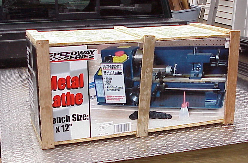
I have received reports from two recent purchasers of the Homier 7x12 lathe that the lathes they received were not as described in my review and as shown in the picture above.
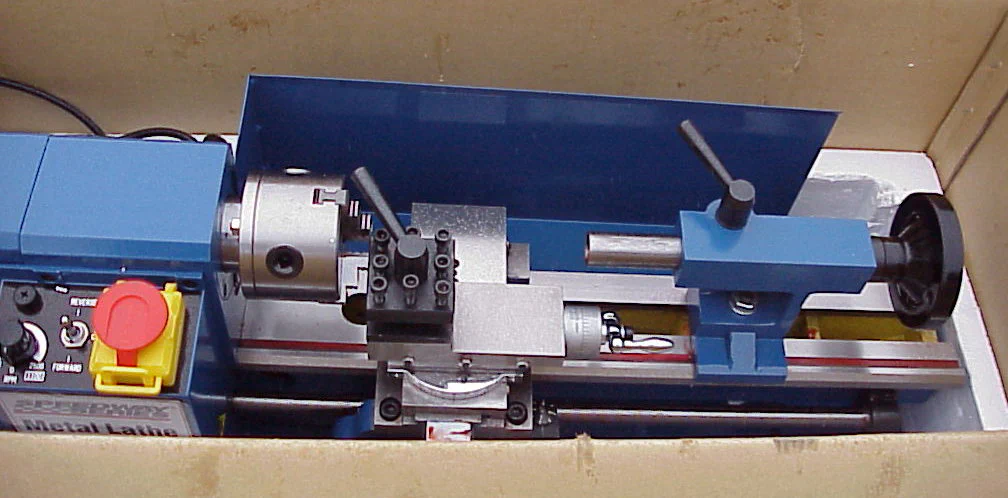
The lathes being shipped now appear to a blue version of the familiar Sieg 7x12 lathe, the same as that sold by Grizzly.
I have requested confirmation of this change directly from Homier, but so far have not received a definitive answer. Update (9/5/02) Homier has confirmed that Sieg is now the supplier of their mini-lathe.
Their representative did state that they had made a vendor change and that some of the features are different, but not explicitly that the new lathes are the Sieg version.
It is also likely that some of the older versions may still be in stock at various Homier sales around the country, so you could end up with either version if you buy one during the next few months.
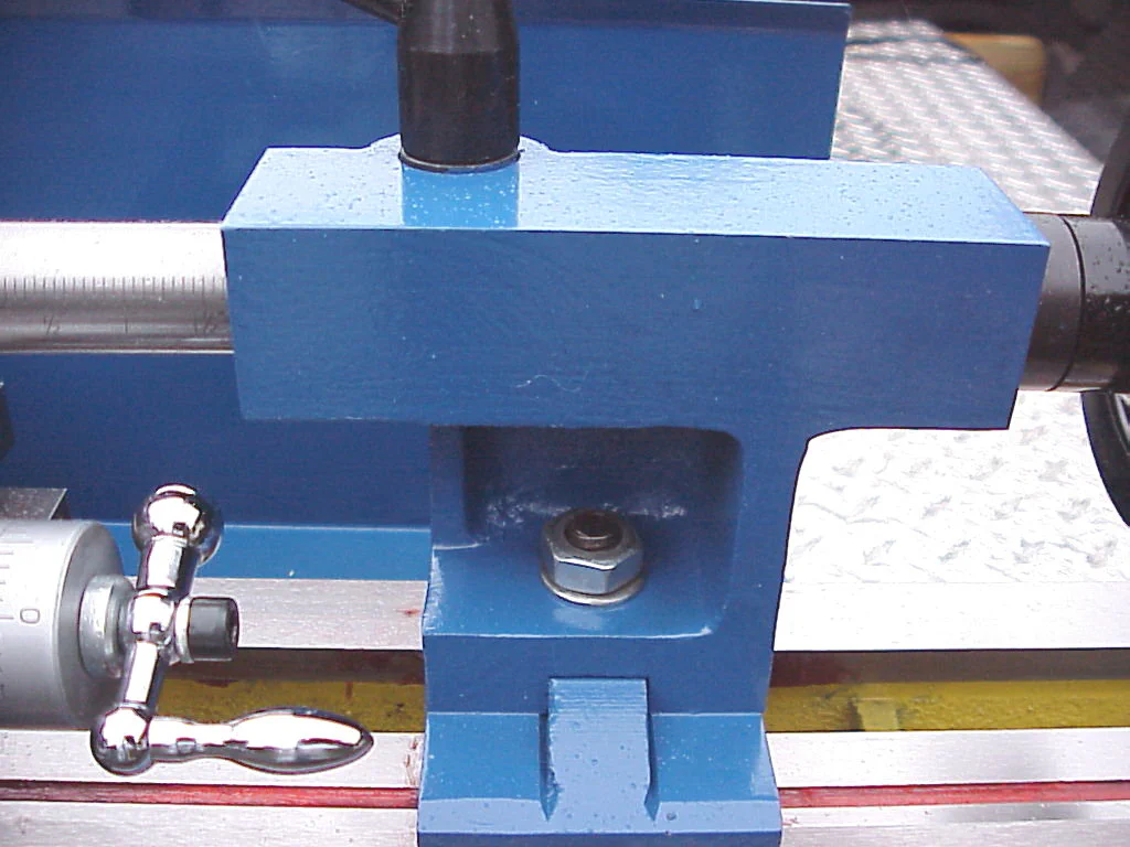
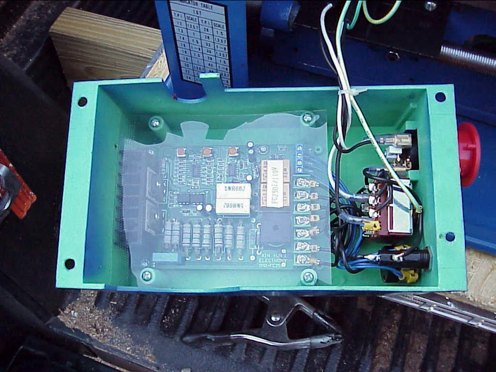
On casual observation the two styles of lathe look similar, but there are a number of details that are different, as summarized in the following table:
| Original Homier Model | Sieg Model | |
|---|---|---|
| Packing grease | light coating of nearly clear grease | thick red grease |
| Saddle | Rectangular shape, bare metal with way wipers and oil ports | H-shaped, painted metal; no way wipers or oil ports |
| Tailstock | No markings on ram, acorn locking nut, flat base not painted | Inch markings on ram, flat locking nut, flat base is painted |
| Power supply | SCR type | MOSFET type |
| Compound and Cross Feed dials | Have locking setscrew | No locking setscrew |
| Protractor | Black plastic | Chrome metal |
| Threading dial | Silver with adjusting screw | Black, no adjusting screw |
| Compound and Cross Feed Handles | Elongated | Not elongated |
| Leadscrew | Adjustable nut on end, extends beyond pillow block | No adjusting nut, flush with pillow block |
| Tool Holder | Plain shiny steel | Black oxide steel |
| Toopost stud | Center portion not threaded | Threaded over entire length |
| Tool size | 3/8" | 5/16" |
| Headstock | 4 bolts attach to bed | 3 bolts attach to bed |
| Spindle | 3 bolt holes (6 on some) | 6 bolt holes |
Here’s some information provided by Al Tyson: (thanks, Al!)
> Just received the Homier Mini Lathe I ordered and discovered that it does
> have the additional 4 holes in the spindle for the 4 jaw chuck. However the
> reason it does is not because they’ve added the additional holes to their
> original machine but because they’ve gone to the SEIG 7 X 12 Mini Lathe.
My
> machine has none of the additional features of your Homier IE: The way
> wipers, the plastic protractor or the additional length on the lead screw
> with the nut and set screw.
It has all the features of the Grizzley 7 X 12,
> IE the metal protractor, the Tail Stock Ram is graduated and it has the
> shorter lead screw with no nut with set screw to take up slack in the lead
> screw.
I have’nt checked whether it’s set up for 5/16 tooling like the HF and
> Grizzley rather than the 3/8 of the original Homier but considering it has
> all the other features of the Grizzley including the fact that the rubber
> mounting feet were NOT installed I’d say it’s a pretty good bet that it’s set
> up for 5/16 tooling as well
> By the way I called Homier & asked them if they changed manufacturers
> and was told they had. Also the parts diagram which is part of the
> instruction manual is the same diagram posted on the Little Machine Shop web
> site as the Grizzley 7 X 12 including all of the parts #s.
Here are some photos sent by Charlie Brighthaupt (thanks, Charlie!)
End of update
I first started hearing about a 7x mini-lathe from Homier around summer of 2001. Like a summer storm rolling in, it began with a distant rumble that grew to a dramatic crescendo as it drew near.
By now quite a few members of the 7x interest group have purchased these lathes and have provided much positive feedback. I was anxious to get my hands on one so that I could do a thorough side-by-side comparison with the well-established Harbor Freight 7x10 and Grizzly 7x12 lathes (I have one of each).
That opportunity arose, and what you are reading here is the result of that analysis.
Since I will continually be comparing the Homier lathe to the other lathes, I will use the acronym TOL to refer to “The Other Lathes” throughout the review.
As a point of reference, the HF and Grizzly lathes are made by the same factory and, aside from the length of the bed and details of the power supply, are practically identical in most respects. By contrast, the Homier lathe is made by a different manufacturer and has a number of features not found on the other two lathes. Refer to the Features page for comparison with the HF 7x10, and to the Setup page for comparison with the Grizzly 7x12.
Which one is better? To find out, you’ll have to read the rest of the review.
As in all my reviews, I try to present a fair and balanced view and report the not so good along with the good. But as you read the following review, keep in mind that this lathe cost $299 as of 04/02.
It’s really quite remarkable that you can get a lathe anywhere near this quality for a price like that!
Receiving and Unpacking
The Homier 7x12 was delivered by UPS and left on my doorstep. That’s standard practice in my neighborhood, and I have never lost a package. This one weighed 95 lbs.
and came in a plain brown outer packing box, so it’s not too likely that anyone would have walked off with it. However, I was home at the time, so I loaded it onto my little luggage cart and wheeled it into my shop in the garage.


Opening the outer box revealed the inner box containing the lathe. Homier obviously has been responsive to reports of damage and is now shipping the lathes with this double box method.
I’m happy to report that mine had no damage except a very minor bend in the chip tray.
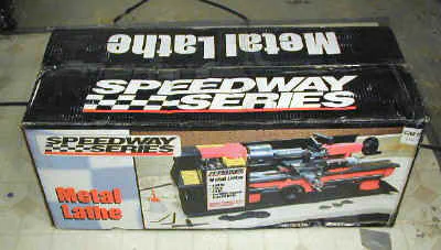
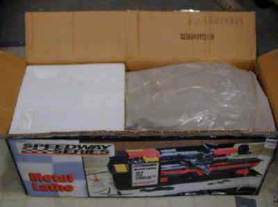
The lathe is securely padded by thick packing paper which cushions the parts inside the box. Some owners have reported receiving the lathe with the tailstock loose in the box, but wrapped in the packing paper.
On mine, the tailstock was securely clamped to the ways, as it should be.
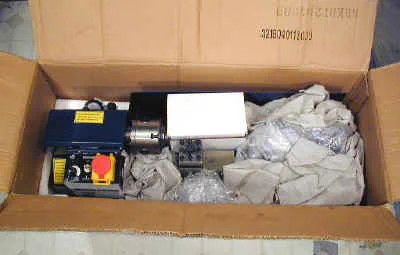
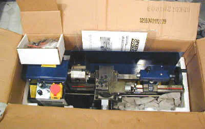
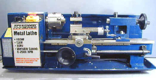
The lathe is a nice-looking deep royal blue color. Here it is on the bench just as it came from the box. The rubber feet are already attached to the lathe, whereas on the Grizzly and HF lathes, they must be mounted by the owner.
Accessories
Inside a small cardboard box can be found the accessories that come with the lathe. The outside chuck jaws and dead center, being prone to rust, are wrapped in rust deterrent oiled paper.
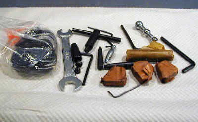
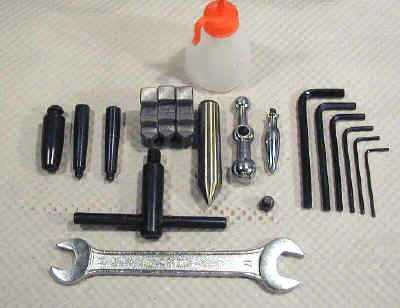
Top to bottom, left to right, the accessories are:
- Plastic oil bottle, handwheel handle, toolpost handle, tailstock lock handle, outside chuck jaws, dead center, cross-feed handle (3 pcs.), Hex wrenches (6 pcs.), chuck wrench, open end wrench. A small open end wrench (10mm) needed to remove the chuck is not provided, so make sure you have one on hand before your lathe arrives.
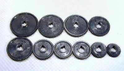
Shown below are the extra change gears. They are made of plastic and are slightly thinner than those provided with the HF and Grizzly lathes.
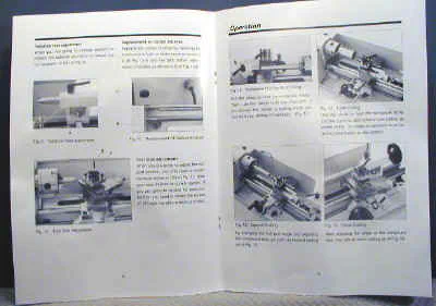
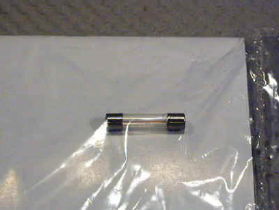
Also included is a 16-page user manual, comparable to those supplied with the HF but a little less detailed than the Grizzly manual. A spare fuse is packed inside the plastic bag containing the user manual.
Cleaning up the Lathe
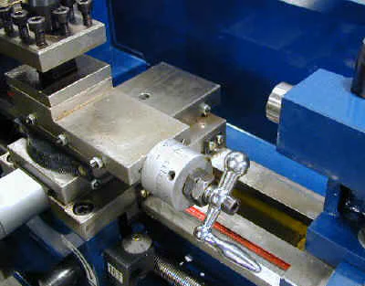
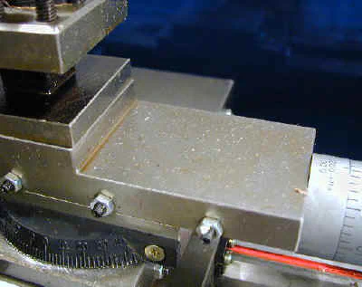
As reported by others, I found the packing grease on the Homier lathe to be very light compared to the thick red gunk on the HF and Grizzly lathes. This makes cleanup a much less daunting task, but I did notice a few small areas of rust, so this grease may not provide quite as much protection as the thick red stuff.
As you will see in the following pictures, the grease is pretty mild:
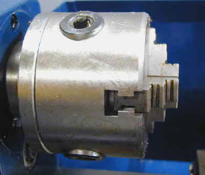
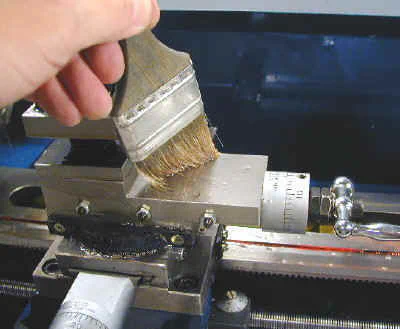
To clean up, I just brushed the surfaces with kerosene and wiped them clean with a cotton rag. A couple of passes and 45 mins. later, the lathe was looking pretty good.
For comparison, here’s a photo of the red grease that protects the Grizzly 7x12:

For more information on cleanup and setup of the 7x lathes, check the setup page.
One thing to watch out for: the kerosene stripped some of the red paint in the grooves of the ways. No big deal, but worth noting if you wish to maintain your lathe in showroom condition.
No problems were encountered with the blue paint.
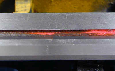
For more information on cleanup and setup of the 7x lathes, check the setup page.
Bed and Ways
One thing that impressed me right off was the quality of the ways. They have a very fine finished appearance with crisp, ground surfaces.
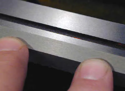
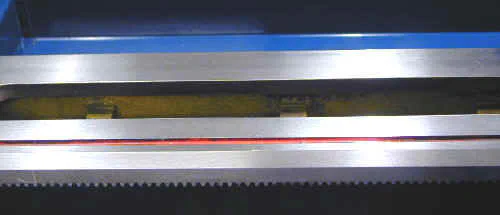
There has been a fair amount of discussion in the 7x10 group about whether the ways on the Homier (and for that matter, on the other 7x lathes) are hardened.
On expensive high-end lathes, the ways essentially are always hardened. This is desirable, since it helps to protect them from dings and gouges which can affect accuracy or cause binding of the carriage as it travels down the ways.

On the end of the bed of the Homier lathe is a little label that reads “Heat Treatment”. This label has led to speculation that the ways are hardened. However, some have interpreted this to mean merely that after casting the ways are heat-annealed to relieve stress in the casting before grinding the ways.
Now, “hardness” is hard to measure without special instruments. For our purposes, the real question is this: “If I drop a wrench on the ways, will it leave a big dent?”.
So I set out – rather unscientifically I might add – to answer this question. Here’s the result: If you whack the top of the compound with a wrench it leaves a dent.
Do the same on the ways and the dent is much smaller - just a mark, really. I repeated this precision test on the other lathes and got pretty much the same result.
So I think that the answer is that the ways are harder than the raw metal of the compound, but not nearly as hard as, say, the chuck jaws. I could not conclude that the ways on the Homier lathe are any harder or softer than those on the other lathes.
Now if one you readers out there could lend me a hardness tester…
Way Wipers
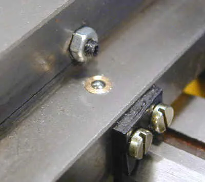
Another feature of this lathe not found on the others is wipers for the ways. These are attached to both sides of the saddle and serve to prevent swarf and chips from working into the gap between the saddle and ways.
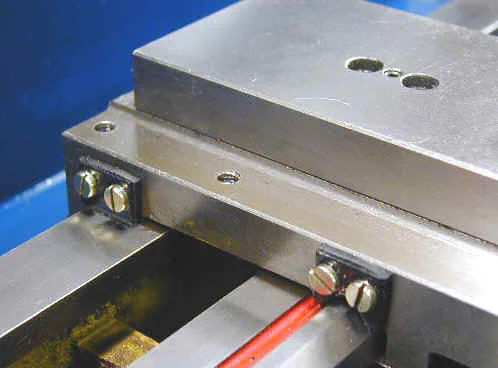
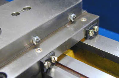
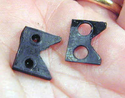
Removing one of the wipers reveals that it consists of a soft rubber wiper held in place by a thin metal cover. Also unique are the ball-bearing sealed oil holes above the wipers on the right side.
Neat feature!
Leadscrew and Half Nut
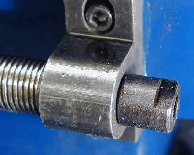
The right end of the leadscrew is terminated by a special nut. At first I thought this might be used to take up any play in the leadscrew, but it seems to lock down leaving a fixed clearance between the face of the nut and the pillow block, so I’m not sure what purpose it serves.
Removing the nut exposes a threaded extension that may be intended for use with an optional hand crank or power feed. Well, even if it was not intended for that use, it sure might lend itself well to such a mod.
![]()
When I removed the pillow block, I discovered that there is a ball-bearing oil port on the underside. Gravity being as it is, I decided that it made more sense for the oil port to be on the top side of the block, so I flipped it over when I reinstalled it.
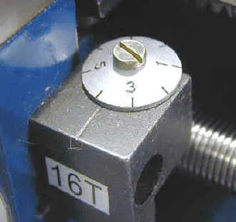
The thread dial has a light finish rather than the black color found on TOL but is otherwise similar. It is used to engage the lead screw at the proper point when thread cutting.
Cross Feed and Compound
The cross-feed and compound are similar in construction to the other 7x lathes, but here again, you will find some differences.
Dials and Handles
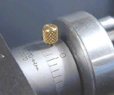
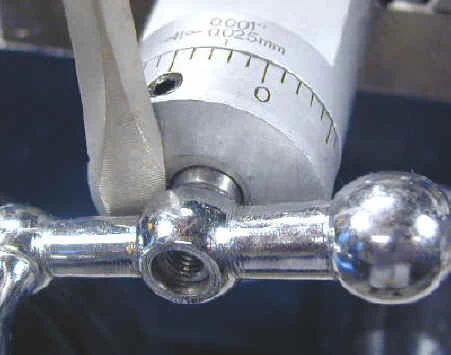
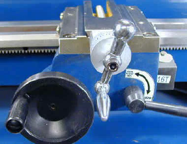
The cross-feed and compound dials are provided with setscrews to lock them at a specific setting rather than the friction spring arrangement found on TOL.
For convenience, I will probably replace the setscrews with little thumb screws so that I don’t have to search for the proper hex key when I want to lock them down.
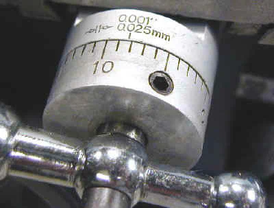
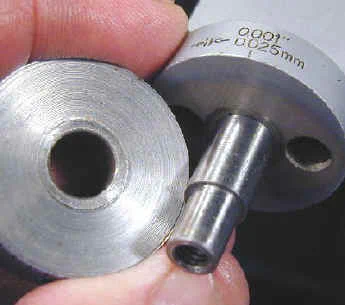
This is a better setup than the friction locking arrangement, since the friction locking ones are subject to slipping. When they slip, it can be really frustrating - especially when you are cutting threads to a specified depth and have no way to reestablish the reference point once you start cutting.
For this reason, in fact, I added this feature to my 7x12 as shown below.
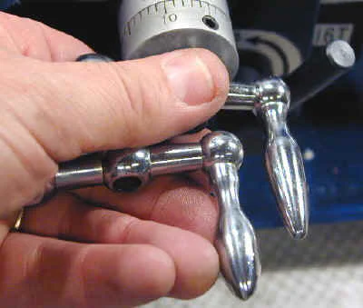
The chrome handles have a slightly different shape than those on TOL. I’m holding a handle from the HF 7x10 in my hand next to the Homier handle.
Be sure to remove the handles and dials and clean the dials, as I found a lot of grit on the back face of the dial. You may need to insert the tip of a screwdriver and twist it to gently pry off the handles.
3-Inch 3-Jaw Chuck
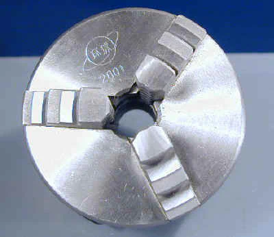
The chuck appears to be identical to those on the HF and Griz lathes, judging from the planet logo and other markings. From my experience with those lathes, I can attest that this is a fine chuck and should do just about anything you would expect from a little chuck on an inexpensive lathe.
It is not unusual for the moving parts to be somewhat stiff until it gets worn in, and this chuck was no exception.
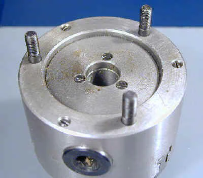
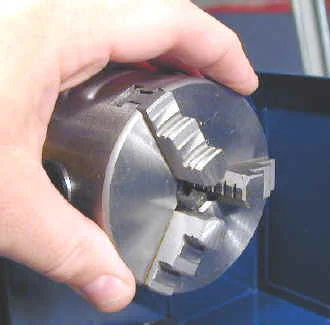
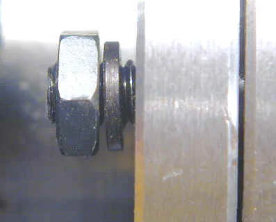
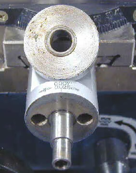
The bottom left hand photo above should give you a good idea of the true size of the chuck. Its small, but you can supplement it with a variety of optional chucks if you need more capacity.
In the bottom right hand photo you can see that lock washers are supplied for the chuck mounting nuts. None are provided on the other 7x lathes, nor needed within my experience.
They’re probably a good idea, though, if you don’t mind fooling with the extra hassle of getting them in place. Captive washers would be nice.
The mounting nuts provided on this lathe are somewhat thinner than those on the other lathes and this makes them a little easier to get into position on the studs within the narrow space between the back of the chuck and the headstock.
Spindle
OK, you’ve all been wondering: does the spindle plate have 3 holes or 6 holes? If you have been following this discussion on the 7x group, or have read my Versions page for the Homier lathe, you already know that the Homier spindle plate only has 3 holes.
Beginning in March, 2002, however, a few new owners reported receiving Homier lathes having the extra 3 holes needed to directly mount a 3" 4-jaw chuck. We have all been hoping that this is a permanent upgrade that can be expected on all future shipments.
Unfortunately, mine only has 3 holes. Of course, it may still be true that lathes manufactured after a certain date have the extra holes and that I simply received one that was made before the cutoff date.
I will see if Homier can shed any light on this matter. The inset on the right below shows the 6-hole spindle plate found on the HF and Griz lathes.
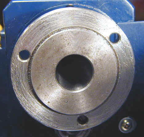
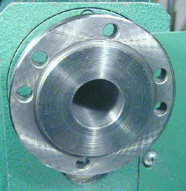
I have to say, that the quality of the surface of the spindle plate was disappointing. In stark contrast to the fine quality finish of the ways, the spindle face has a very rough finish.
Adding a little more salt to this particular wound, there was considerable swarf and grit in the recesses of the spindle.
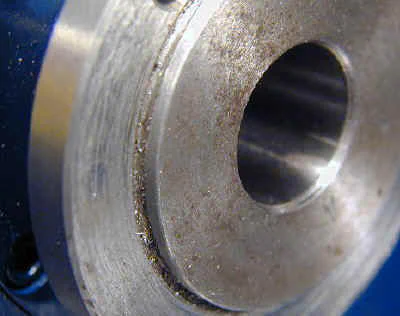
OK, griping aside, what’s the real impact? Drilling the extra holes for the 4-jaw chuck should be pretty straightforward using a hand-held drill. The swarf can be cleaned up with a brush, so has no detrimental effect other than to cause a little disappointment with the quality.
The rough surface of the spindle face can be cleaned up and trued up with a couple of fine facing cuts. So, when all is said and done, these issues are really pretty minor.
You have to expect some tradeoffs like this when you buy a low-cost machine tool. If you found a ‘57 Chevy with a little rust on it sitting in a barn somewhere, and were able to buy it for $300, you probably would not complain much about the rust.
It’s kinda like that.
Spindle and Chuck Runout
Spindle runout is the extent to which the spindle bore is not exactly concentric with the center of rotation. It is one of the most important factors in determining the overall accuracy of the lathe, since no cut can be made to a precision greater than the runout.
I measured the runout on the inside of the spindle bore and found it to be less than .0005; around .0002 as well as I could estimate with my dial test indicator.
This is surprisingly good for a lathe in this price range.
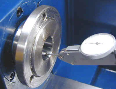
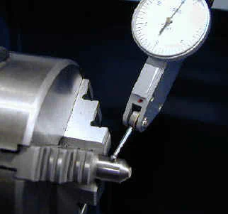
Next I measured the runout near the chuck by clamping a 3/8" shank end mill in the chuck and measuring against the round surface of the shank. Initially I measured .
009" runout, which is not very good. A runout of around .003 or less is what we would like to see.
I removed the chuck, carefully brushed the spindle and the back surface of the chuck to remove any swarf or grit, then remounted the chuck and tested again.
This time I measured the runout at just under .002" so the first reading may have been skewed by a piece of sand or grit between the chuck and spindle plate.
Tailstock

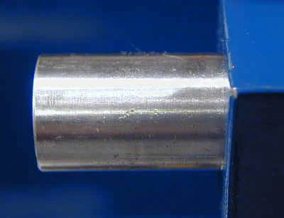
Features of the tailstock that differ from TOL are as follows:
- No graduations on ram
- Improved setover arrangement
- Acorn cap nut to lock tailstock in place
- Oil access hole for ram
- Bed stop to keep tailstock from falling off end of bed
I was a little surprised that there were no graduations on the ram to indicate drilling depth. This is not much of a loss, in fact, since they are difficult to read anyway on TOL. In practice I use my little depth gage for approximate depths and a dial indicator for precise work.
One method for cutting long tapers is to turn between centers with the tailstock offset laterally. On TOL, this is awkward at best, because the lock screw is on the underside of the tailstock casting.
On the Homier, the lock screws are on the rear of the tailstock - a much better arrangement. There is a little gage to help estimate the setover and reset to center, but I doubt that it would be accurate enough to be of much value in actual practice.
I found the tailstock alignment to be quite good, right out of the box. I mounted the dead center in the tailstock and a piece of 3/8" drill rod turned to a point in the chuck and brought the together.
As you can see in the photo, they meet up point-to-point.
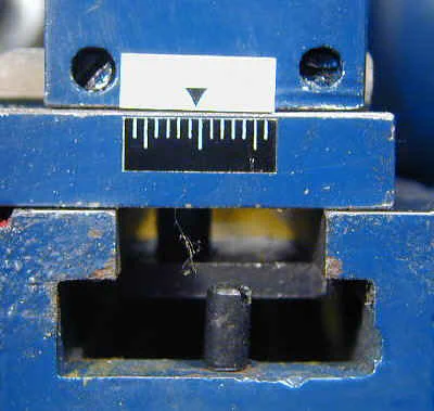
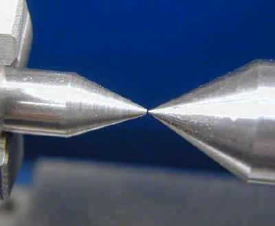
If you look carefully you can see the stop screw in the groove in the bed just below. I assume that this is to prevent you from accidentally sliding the tailstock off the end of the bed.
I routinely remove mine when its not in use to gain the extra room, so I will be removing this little guy first thing.
Bed and Ways
The bed is sturdy cast iron with the usual rough finish on the less visible surfaces.
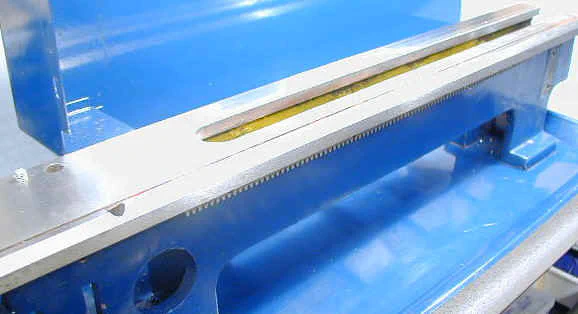
One thing that impressed me right off was the quality of the ways. They have a very fine finished appearance with crisp, ground surfaces.

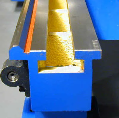
There has been a fair amount of discussion in the 7x10 group about whether the ways on the Homier (and for that matter, on the other 7x lathes) are hardened.
On expensive high-end lathes, the ways essentially are always hardened. This is desirable, since it helps to protect them from dings and gouges which can affect accuracy or cause binding of the carriage as it travels down the ways.

On the end of the bed of the Homier lathe is a little label that reads “Heat Treatment”. This label has led to speculation that the ways are hardened. However, some have interpreted this to mean merely that after casting the ways are heat-annealed to relieve stress in the casting before grinding the ways.
Now, “hardness” is hard to measure without special instruments. For our purposes, the real question is this: “If I drop a wrench on the ways, will it leave a big dent?”.
So I set out – rather unscientifically I might add – to answer this question. Here’s the result: If you whack the top of the compound with a wrench it leaves a dent.
Do the same on the ways and the dent is much smaller - just a mark, really. I repeated this precision test on the other lathes and got pretty much the same result.
So I think that the answer is that the ways are harder than the raw metal of the compound, but not nearly as hard as, say, the chuck jaws. I could not conclude that the ways on the Homier lathe are any harder or softer than those on the other lathes.
Now if one you readers out there could lend me a hardness tester…
Gear Train and Levers
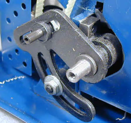
Looking at the left side of the lathe you will see the cover for the gear train. Removing the two bolts at the top of the cover releases it and reveals the gear train.
The arrangement is essentially the same as on TOL.
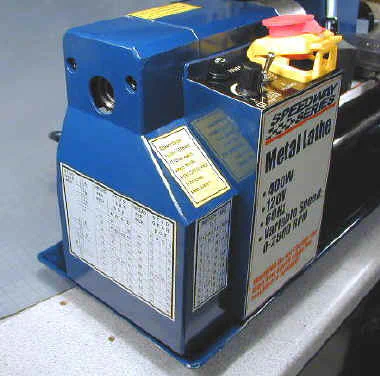
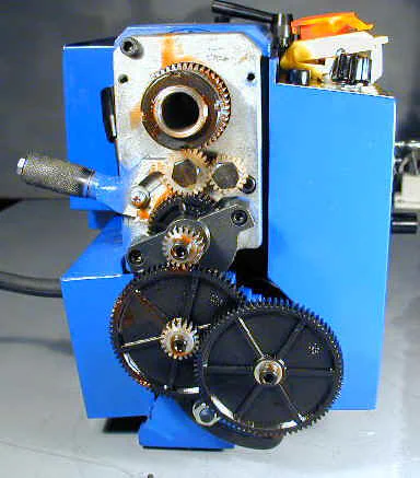
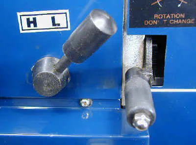
On the back side of the headstock are located the Hi/Lo range selector lever and the leadscrew drive lever. The Hi/Lo range lever shifts gears inside the headstock to change the upper RPM limit from around 1200 in low range to about 2500 in high range.
Hi range is typically used for polishing rather than cutting operations.
The leadscrew lever is shifted by pulling back on the knurled sleeve and then moving the lever up or down into one of three detents:
- UP - carriage moves towards headstock
- MID - leadscrew does not turn (neutral)
- DOWN - carriages moves away from headstock
Leadscrew
As on the TOL, the leadscrew is 16 TPI. The right end is terminated by a special nut. At first I thought this might be used to take up any play in the leadscrew, but it seems to lock down leaving a fixed clearance between the face of the nut and the pillow block, so I’m not sure what purpose it serves.
Update 4/14/02
Gregg Eshelman pointed out to me that there is a setscrew in the nut which engages with the end of the leadscrew. Adusting the setscrew thus adjusts the clearance between the face of the nut and the side of the pillow block, so the nut can, indeed, take up any slop in the leadscrew.
End of update
Removing the nut exposes a threaded extension that might lend itself well to use with an optional hand crank or power feed.

![]()
When I removed the pillow block, I discovered that there is a ball-bearing oil port on the underside. Gravity being as it is, I decided that it made more sense for the oil port to be on the top side of the block, so I flipped it over when I reinstalled it.
Half Nut and Thread Dial
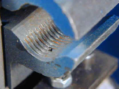
The half nut clamps around the lead screw to drive the carriage under power. I was impressed by the crisp engagment of the half nut lever. On both of my other mini lathes the half nut has a somewhat mushy feel.
Looking at the threads on the half nut, it appears that they are cut more cleanly on this lathe, and that may account for the difference in feel.

The thread dial has a light finish rather than the black color found on TOL but is otherwise similar. It is used to engage the lead screw at the proper point when thread cutting.
Carriage and Saddle
The carriage rides along the ways and supports the cross-slide and compound. The saddle is the horizontal piece that rides on the ways and the apron is the vertical piece on which the carriage handwheel, drive gears, half-nut lever and half-nut are mounted.
The handwheel is made from plastic but not the Bakelite type used on TOL.
The carriage can be moved rapidly by hand using the carriage handwheel, which engages with a rack along the underside of the ways. Movement was pretty smooth, with no apparent binding.
The carriage can also be moved under power feed to obtain a smooth, even finish on a turning operation, or when cutting threads. When the leadscrew is being driven by the gear train, twisting the half nut lever to the DOWN position engages the leadscrew; UP disengages.
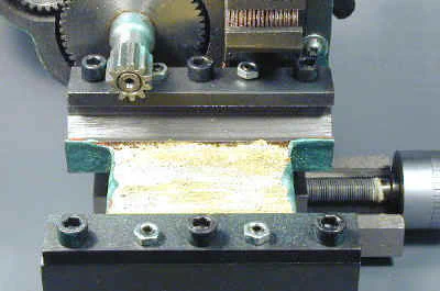
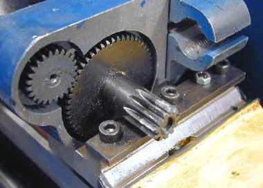
Removing the carriage and inverting it reveals the drive gears and the half-nut. The saddle is retained on the ways be two metal strips with adjusting screws to set the clearance - the same arrangment used on TOL.
Way Wipers
A nice feature of this lathe not found on the others is wipers for the ways. These are attached to both sides of the saddle and serve to prevent swarf and chips from working into the gap between the saddle and ways.


Removing one of the wipers reveals that it consists of a soft rubber wiper held in place by a thin metal cover. Also unique are the ball-bearing sealed oil holes above the wipers on the right side.


Cross Slide
The cross-slide is similar in construction to TOL but I would rate the machining as better quality.
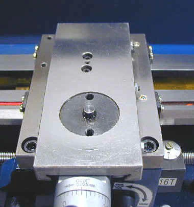
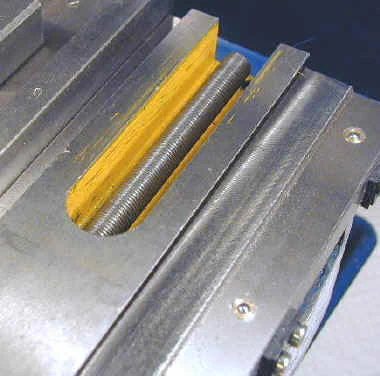
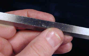
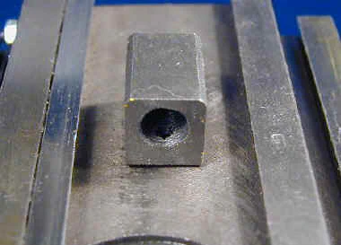
The cross feed nut is cast iron rather than brass, but the backlash adjustment is the same. The finish on the gib bearing surface was definitely better than I am used to seeing.
Compound
Mounted on the cross-slide, the compound can rotate and be locked at an angle for cutting short tapers or threads. As on TOL, the locking screws are underneath the compound slide, so you must crank the slide nearly all the way back to gain access to the locking screws.
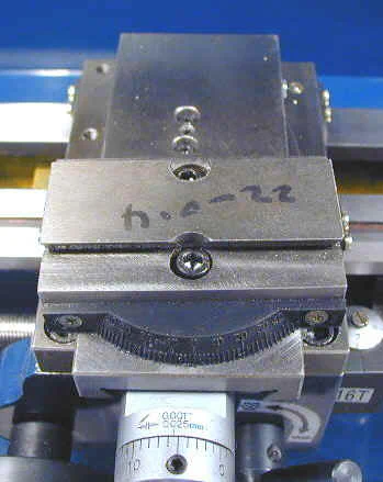
The dovetails were nicely finished, but I found quite a lot of swarf and grit in the grooves, so be sure to clean this area thoroughly with a brush and some kerosene.
Then apply a liberal amount of light oil or white lithium grease to lubricate the slide.
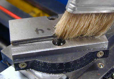
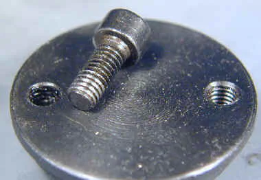
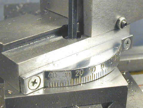
I also discovered a small manufacturing defect: one of the bolt holes in the compound swivel plate was not threaded properly (the hole on the left in the photo above) and the locking screw could not be tightened down.
I first tried tapping the hole to 6x1mm, the original thread size, but the bolt still did not get a bite on the threads, so I tapped it out to 1/4-20 and replaced the bolt.
That did the trick.
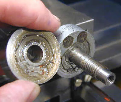
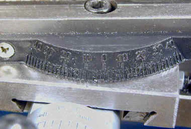
Interestingly, while the dial on the cross-slide had no grease on it at all, the compound dial had a thick coating of grease. The protractor is made of plastic and I found it a little hard to read compared to the cast metal ones on TOL.
Dials and Handles
The cross-feed and compound dials are provided with setscrews to lock them at at a specific setting rather than the friction spring arrangement found on TOL.
For convenience, I will probably replace the setscrews with little thumb screws so that I don’t have to search for the proper hex key when I want to lock them down.


This is a better setup than the friction locking arrangement, since the friction locking ones are subject to slipping. When they slip, it can be really frustrating - especially when you are cutting threads to a specified depth and have no way to reestablish the reference point once you start cutting.
For this reason, in fact, I added this feature to my 7x12 as shown below.
The chrome handles have a slightly different shape than those on TOL. I’m holding a handle from the HF 7x10 in my hand next to the Homier handle.


Be sure to remove the handles and dials and clean the dials, as I found a lot of grit on the back face of the dial. You may need to insert the tip of a screwdriver and twist it to gently pry off the handles.


3-Inch 3-Jaw Chuck
The chuck appears to be identical to those on the HF and Griz lathes, judging from the planet logo and other markings. From my experience with those lathes, I can attest that this is a fine chuck and should do just about anything you would expect from a little chuck on an inexpensive lathe.
It is not unusual for the moving parts to be somewhat stiff until it gets worn in, and this chuck was no exception.


The bottom left hand photo above should give you a good idea of the true size of the chuck. Its small, but you can supplement it with a variety of optional chucks if you need more capacity.
In the bottom right hand photo you can see that lock washers are supplied for the chuck mounting nuts. None are provided on the other 7x lathes, nor needed within my experience.
They’re probably a good idea, though, if you don’t mind fooling with the extra hassle of getting them in place. Captive washers would be nice.
The mounting nuts provided on this lathe are somewhat thinner than those on the other lathes and this makes them a little easier to get into position on the studs within the narrow space between the back of the chuck and the headstock.
Tailstock


Features of the tailstock that differ from TOL are as follows:
- Two locking screws for setover
- No graduations on ram
- Acorn cap nut to lock tailstock in place
- Oil access hole for ram
- Bed stop to keep tailstock from falling off end of bed
I was a little surprised that there were no graduations on the ram to indicate drilling depth. This is not much of a loss, in fact, since they are difficult to read anyway on TOL. In practice I use my little depth gage for approximate depths and a dial indicator for precise work.
I found the tailstock alignment to be quite good, right out of the box. I mounted the dead center in the tailstock and a piece of 3/8" drill rod turned to a point in the chuck and brought them together.
As you can see in the photo, they meet up point-to-point.


If you look carefully you can see the stop screw in the groove in the bed just below. I assume that this is to prevent you from accidentally sliding the tailstock off the end of the bed.
I routinely remove mine when its not in use to gain the extra room, so I will be removing this little guy first thing.
Toolpost
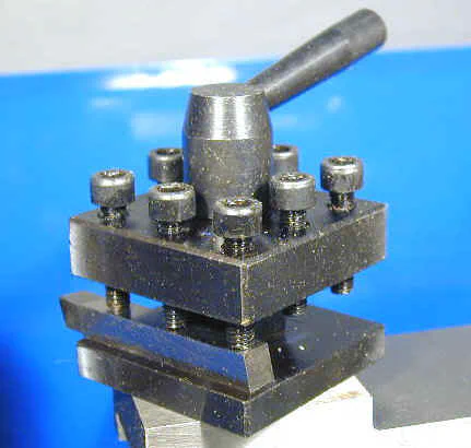
The toolpost has a plain metal finish rather than black oxide. Though essentially the same dimensions as on TOL, the toolpost is mounted about 0.10" lower and is therefore better suited to 3/8" tool bits instead of the 5/16" bits used on TOL. I found that even a 3/8" bit was below the centerline and had to be shimmed. The underside of the tool holder has notches that engage with a spring-loaded detent to lock the holder at one of four positions. TOL have this feature, but I have routinely removed the spring and pin so that I can easily set the holder to any angle I want.
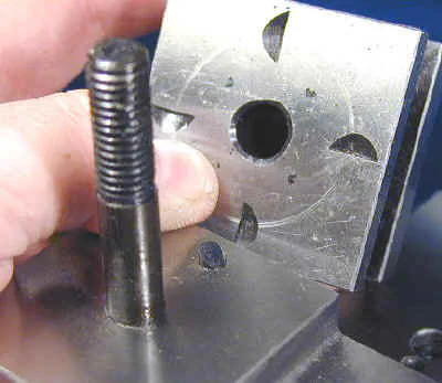
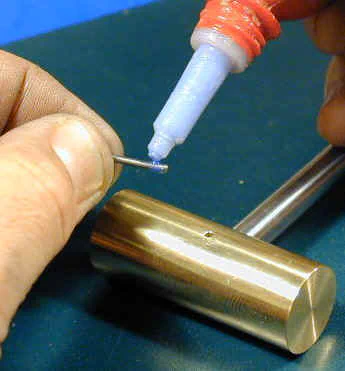
A drop of Loctite on the threads of the handle will prevent it from twisting loose in use. I use Loctite on all the handle threads throughout the lathe.
Spindle
OK, you’ve all been wondering: does the spindle plate have 3 holes or 6 holes? If you have been following this discussion on the 7x group, or have read my Versions page for the Homier lathe, you already know that the Homier spindle plate only has 3 holes. Beginning in March, 2002, however, a few new owners reported receiving Homier lathes having the extra 3 holes needed to directly mount a 3" 4-jaw chuck. We have all been hoping that this is a permanent upgrade that can be expected on all future shipments.
Unfortunately, mine only has 3 holes. Of course, it may still be true that lathes manufactured after a certain date have the extra holes and that I simply received one that was made before the cutoff date.
I will see if Homier can shed any light on this matter. The inset on the right below shows the 6-hole spindle plate found on the HF and Griz lathes.


I have to say, that the quality of the surface of the spindle plate was disappointing. In contrast to the fine quality finish of the ways, the spindle face has a very rough finish.
Adding a little more salt to this particular wound, there was considerable swarf and grit in the recesses of the spindle.

OK, griping aside, what’s the real impact? Drilling the extra holes for the 4-jaw chuck should be pretty straightforward using a hand-held drill. The swarf can be cleaned up with a brush, so has no detrimental effect other than to cause a little disappointment with the quality.
The rough surface of the spindle face can be cleaned up and trued up with a couple of fine facing cuts. So, when all is said and done, these issues are really pretty minor.
You have to expect some tradeoffs like this when you buy a low-cost machine tool. Assume that you are a person who likes to restore old cars. If you found a ‘57 Chevy with a little rust on it sitting in a barn somewhere, and were able to buy it for $300, you probably would not complain much about the rust.
It’s kinda like that.
Spindle and Chuck Runout
Spindle runout is the extent to which the spindle bore is not exactly concentric with the center of rotation. It is one of the most important factors in determining the overall accuracy of the lathe, since no cut can be made to a precision greater than the runout.
I measured the runout on the inside of the spindle bore and found it to be less than .0005; around .0002 as well as I could estimate with my dial test indicator.
This is surprisingly good for a lathe in this price range.


Next I measured the runout near the chuck by clamping a 3/8" shank end mill in the chuck and measuring against the round surface of the shank. Initially, I measured .
009" runout, which is not very good. A runout of around .003 or less is what we would like to see.
I removed the chuck, carefully brushed the spindle and the back surface of the chuck to remove any swarf or grit, then remounted the chuck and tested again.
This time I measured the runout at just under .002" so the first reading may have been skewed by a piece of sand or grit between the chuck and spindle plate.
Electronic Controls
As on TOL, the controls are mounted atop a plastic housing mounted on the front of the headstock. The power supply circuit board is mounted inside the plastic housing, exposing it to the same risk of being shorted by metal chips that many of us have experienced.
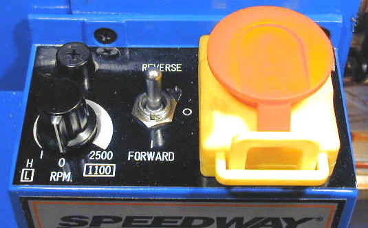
The control panel includes the following items:
- Fuse holder
- Speed control and reset knob
- Forward / Neutral / Reverse switch
- Power / Emergency cutoff switch
Following the standard set by the Grizzly 7x12, the speed control must be reset to zero before the lathe can be started or the direction reversed. This is a desirable safety feature which prevents the spindle from starting up at high speed if you happened to have left the speed control knob set there.
It also serves this purpose should there be a power failure or tripped circuit breaker.
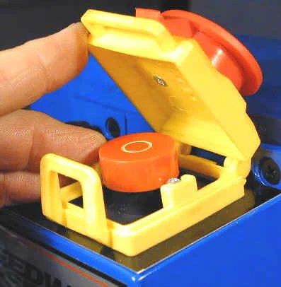
The BIG RED BUTTON (BRB) acts as the main power switch as well as an emergency ‘panic-button’. To cut off the power, you must depress the outer cap until the yellow cover latches shut.
To childproof the lathe you can insert a small (luggage-style) padlock in the loop of the yellow cover. Pressing back on the cover unlatches the lid and turns on the power.
Underneath the cover is another BRB that does the real work. The outer one just presses on the inner one.
In an emergency, if you mash down on the red button, it will shut off the power and stop the lathe. However, I have found on the Griz lathe and mill, which both have the BRB, that this does not always work quite as well as it should - if you release the button right away the lathe may not stop.
Power Supply
If you remove the electronics box from the headstock and turn it over you will see the power supply covered by a fiber sheet intended to keep metal chips from shorting out the circuitry.
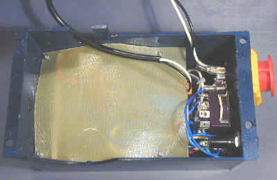
Much debate and speculation has surrounded the Homier power supply. SCR’s (Silicon Controlled Rectifiers) are at the center of this controversy as they are used instead of the Power MOSFETS (Metal Oxide Semiconductor Field Effect Transistors) used on TOL. (For more information on the difference, see the Speed Controls page.) At the heart of all of this is the premise that power supplies based on SCRs provide inadequate torque at low RPMs due to the way the power is switched on and off to the motor in rapid pulses. I have certainly found that to be true for power supplies that use just 2 SCRs, but this one uses 5 and is obviously a very sophisticated circuit, based on the number of components.
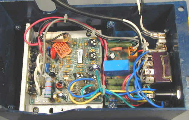
Well, I’m no expert on power supply design, but I can tell you this: the Homier has pretty good torque at low speed, quite comparable to, but maybe a little less than the Grizzly 7x12.
I measured the minimum speed using a stopwatch and determined it to be about 34 RPM. At this speed the torque was very weak - I could easily stop the spindle by gripping it in my hand.
Turn the speed up to about 50-60 RPM, though, and torque ramps up dramatically. At these speeds you must really clamp down hard on the spindle to bring it to a stop (subjective Prony Brake).
On TOL, the power supply has earned a reputation for being the Achilles Heel. Chips ride in on the leadscrew, work their way behind the protective cover sheet and ZAP! Sometimes the boards apparently fail due to overload.
The usual symptom is that the motor will only run at full speed, due to blown MOSFETS. Time will tell how the Homier board holds up under fire but the SCRs may well prove to be more robust than the MOSFETs.
Motor
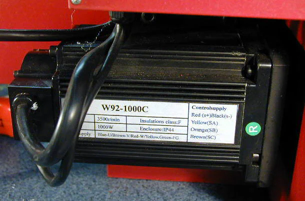
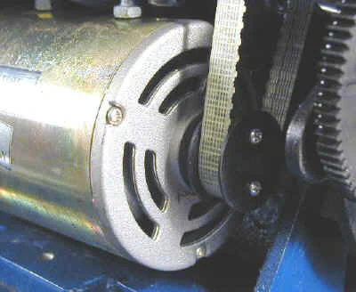
The motor is labeled as 90 VDC, 400 Watts and probably equivalent in actual power despite variations in HP claimed in the ads. It is somewhat different in appearance from those on TOL, but is basically the same type and size.
The height and angle of the motor are set by two bolts threaded into the casting above the motor recess. A translucent toothed fiber belt delivers power from the motor to the drive shaft in the headstock.
Conclusion
Well, that completes our tour of the Homier 7x12 mini-lathe. As is typical of all of the low-cost imported machine tools, the Homier lathe has a few cosmetic flaws and manufacturing defects.
Usually, these are minor enough that you can easily fix them yourself. If you discover a more serious problem, you will have to rely on the vendor to replace the part or the entire lathe.
My own dealings with Homier have been very positive. I have received prompt, courteous responses to all of my emails. All of the reports I have seen on the 7x group have demonstrated that Homier stands behind the products they sell and will quickly replace any defective parts under warranty.
In the final analysis, my opinion is that this may well be the world’s best lathe bargain. If you buy one, as long as you accept its limitations, I believe you will be well pleased and enjoy many years of service.