Turning Operations
Turning is the removal of metal from the outer diameter of a rotating cylindrical workpiece.
Turning is used to reduce the diameter of the workpiece, usually to a specified dimension, and to produce a smooth finish on the metal. Often the workpiece will be turned so that adjacent sections have different diameters.
Chucking the Workpiece
We will be working with a piece of 3/4″ diameter 6061 aluminum about 2 inches long. A workpiece such as this which is relatively short compared to its diameter is stiff enough that we can safely turn it in the three jaw chuck without supporting the free end of the work.

For longer workpieces we would need to face and center drill the free end and use a dead or live center in the tailstock to support it. Without such support, the force of the tool on the workpiece would cause it to bend away from the tool, producing a strangely shaped result.
There is also the potential that the work could be forced to loosen in the chuck jaws and fly out as a dangerous projectile.
Insert the workpiece in the 3-jaw chuck and tighten down the jaws until they just start to grip the workpiece. Rotate the workpiece to ensure that it is seated evenly and to dislodge any chips or grit on the surface that might keep it from seating evenly.
You want the workpiece to be as parallel as possible with the center line of the lathe. Imagine an exaggerated example where the workpiece is skewed at a angle in the chuck and you can easily visualize why this is important. Tighten the chuck using each of the three chuck key positions to ensure a tight and even grip.
Adjusting the Tool Bit
Choose a tool bit with a slightly rounded tip, like the one described above in the tool grinding section. This type of tool should produce a nice smooth finish.
For more aggressive cutting, if you need to remove a lot of metal, you might choose a tool with a sharper tip. Make sure that the tool is tightly clamped in the toolholder.
Adjust the angle of the toolholder so the the tool is approximately perpendicular to the side of the workpiece. Because the front edge of the tool is ground at an angle, the left side of the tip should engage the work, but not the entire front edge of the tool.
The angle of the compound is not critical; I usually keep mine at 90 degrees so that the compound dial advances the work .001″ per division towards the chuck.

Make sure the half nut lever is disengaged and, if you have one, that the carriage lock is not tightened down. If necessary, back off the cross slide until the tip of the tool is back beyond the diameter or the work.
Move the carriage until the tip of the tool is near the free end of the workpiece, then advance the cross slide until the tip of the tool just touches the side of the work. Move the carriage to the right until the tip of the tool is just beyond the free end of the work.
Cutting Speeds
If you read many books on machining you will find a lot of information about the correct cutting speed for the movement of the cutting tool in relation to the workpiece. You must consider the rotational speed of the workpiece and the movement of the tool relative to the workpiece.
Basically, the softer the metal the faster the cutting. Don’t worry too much about determining the correct cutting speed: working with the 7×10 for hobby purposes, you will quickly develop a feel for how fast you should go.
Until you get a feel for the proper speeds, start with relatively low speeds and work up to faster speeds. One of the great features of the 7×10 is that you can adjust the rotational speed without stopping to change belts or gears.
Most cutting operations on the 7×10 will be done at speeds of a few hundred RPM – with the speed control set below the 12 O’clock position and with the HI/LO gear in the LO range. Higher speeds, and particularly the HI range, are used for operations such as polishing, not cutting.
Setting Speed and Feed
The HI/LO range lever on the back of the headstock should be in the LO range for just about all machining operations other than polishing. Set the leadscrew direction on the back of the headstock in the neutral (center) position for now.
If its not already on, turn on the power to the lathe using the red rocker switch. Set the speed control to minimum speed and turn on the lathe motor by moving the silver toggle switch to the FORWARD position. Advance the speed control knob to about the 10 O’clock position (around 400-600 RPM).
Turning with Hand Feed
As always, wear safety glasses and keep your face well away from the work since this operation will throw off hot chips and/or sharp spirals of metal.

Now advance the cross slide crank about 10 divisions or .010″ (ten one-thousandths or one one-hundredth of an inch). Turn the carriage handwheel counter clockwise to slowly move the carriage towards the headstock.
As the tool starts to cut into the metal, maintain a steady cranking motion to get a nice even cut. It’s difficult to get a smooth and even cut turning by hand.
Continue advancing the tool towards the headstock until it is about 1/4″ away from the chuck jaws. Obviously you want to be careful not to let the tool touch the chuck jaws!
Without moving the cross slide or compound, rotate the carriage handwheel clockwise to move the tool back towards the free end of the work. You will notice that the tool removes a small amount of metal on the return pass.
Advance the cross slide another .010 and repeat this procedure until you have a good feel for it. Try advancing the cross slide by .020 on one pass. You will feel that it takes more force on the carriage hand wheel when you take a deeper cut.
Turning with Power Feed
One of the great features of the 7×10 is that it has a power leadscrew driven by an adjustable gear train. The leadscrew can be engaged to move the carriage under power for turning and threading operations.
Turning with power feed will produce a much smoother and more even finish than is generally achievable by hand feeding. Power feed is also a lot more convenient than hand cranking when you are making multiple passes along a relatively long workpiece.

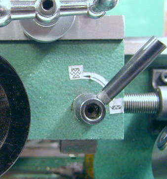
The power feed is engaged by the knurled tumbler gear lever on the back of the headstock. To change the lever setting you must pull back on the knurled sleeve with considerable force. With the sleeve pulled back you can move the lever up and down to engage its locking pin in one of three positions.
In the center position the leadscrew is not engaged and does not turn. In the upper position the leadscrew rotates to move the carriage towards the headstock and in the lower position the leadscrew moves the carriage away from the headstock.
For turning, you will generally want to cut towards the headstock, so move the lever to the upper position and release the sleeve to engage the locking pin.
In the down position, the half-nut lever engages two halves of a split nut around the leadscrew. Make sure the half-nut lever is in the disengaged (up) position. Turn the motor on. The leadscrew should now be rotating counterclockwise.
When the leadscrew is engaged the gear train makes kind of an annoying noise, but you’ll get used to it. Lubricating the gear train with white lithium grease will cut down some on the noise.
With the tool positioned just beyond the end of the workpiece and advanced to make a cut of .010, engage the half-nut lever. The carriage should move slowly to the left under power from the leadscrew. When the tool gets to within about 1/4″ of the chuck, disengage the half-nut to stop the carriage motion.
Now you can use the carriage handwheel to crank the carriage back to the starting point by hand. If you do so without first retracting the cutting tool, you will see that the tool cuts a shallow spiral groove along the workpiece.
To avoid this, especially during finishing cuts, note the setting on the cross-slide dial, then turn the cross feed crank a half turn or so counterclockwise to retract the tool. Now crank the carriage back to the starting point by hand, advance the cross-slide back to the original dial setting plus an additional .010 and repeat the process. You should get a nice, shiny, smooth finish.
Just as in facing, you normally will make one or more relatively deep (.010-.030) roughing cuts followed by one or more shallow (.001-.002) finishing cuts. Of course you have to plan these cuts so that the final finishing cut brings the workpiece to exactly the desired diameter.

When cutting under power, you must be very careful not to run the tool into the chuck. This seems to happen to everyone at one time or another, but it can shatter the tool and damage the chuck and will probably ruin the workpiece.
There is also potential to damage the half-nut, leadscrew or other parts of the power train, so pay close attention and keep your hand ready on the half nut lever.
Measuring the Diameter
Most of time, a turning operation is used to reduce the workpiece to a specified diameter. It is important to recognize that, in a turning operation, each cutting pass removes twice the amount of metal indicated by the cross slide feed divisions.
This is because you are reducing the radius of the workpiece by the indicated amount, which reduces the diameter by twice that amount. Therefore, when advancing the cross slide by .010″, the diameter is reduced by .020″.
The diameter of the workpiece is determined by a caliper or micrometer. Micrometers are more accurate, but less versatile. You will need a machinist’s caliper capable of measuring down to .001″. Vernier calipers do not have a dial and require you to interpolate on an engraved scale.
I prefer a dial caliper which gives a direct easy-to-read and hard-to-misinterpret measurement. Fortunately, good quality Chinese 6″ dial calipers are now available for under $20 from suppliers such as Enco or J&L.
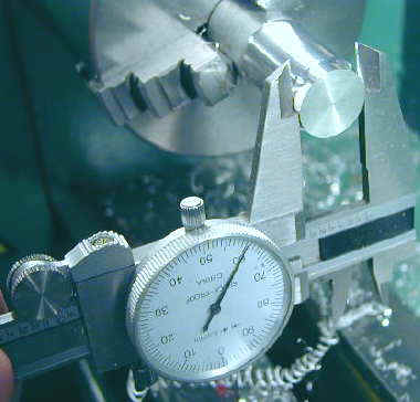
It should be self-evident that you should never attempt to measure the work while it is in motion. With the lathe stopped, bring the dial caliper up to the end and use the roller knob to close the caliper jaws down on the workpiece.
I try to use the tips of the caliper since they are thinner. Gripping the work in the thicker portion of the caliper jaws can force the jaws apart a few thous if you twist the caliper even a small amount.
I like to take an initial reading of the dial while it is still gripping the work since it is easy to inadvertently twist the caliper when removing it, thus changing the reading. You can use the locking screw on the caliper to help prevent this. Slide the jaws straight off the workpiece being careful not to twist the caliper.
Its a good idea to take at least two separate measurements just to make sure you got it right. As it turns out (no pun intended) its much easier to remove metal than it is to put it back 😉
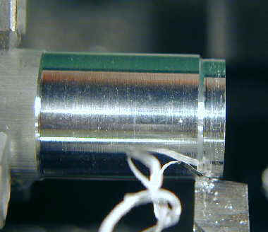
Turning a Shoulder
A shoulder is a point at which the diameter of the workpiece changes with no taper from one diameter to the other. In other words, there is a 90 degree face moving from one diameter to the other as you can see in the next photograph.

We will make a shoulder on our workpiece by reducing the diameter of the end of the workpiece for a distance of about 1/2″.
Advance the cross slide about .020 and use power feed to turn down about a 1/2″ length on the end of the workpiece. Repeat this a few more times until you have reduced the diameter of the end section to about 1/2″.

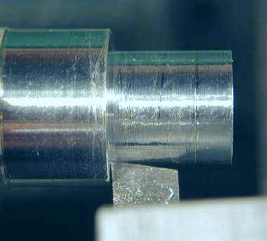
Since the tip of the tool is rounded, the inner edge of the shoulder takes on a rounded profile.

To get a nice square edge we must switch to a tool with a sharp point ground to an angle of less than 90 degrees so that it can work right down into the corner of the shoulder.

Now we will use this pointed tool to make a square finishing cut into the corner of the shoulder. Since this is such a short distance, we will use hand feed, not power feed. You can use hand feed with the leadscrew turning – just don’t engage the half-nut.
To get a nice square face on the shoulder you will need to make a facing cut. This works best if you have made a carriage lock on your lathe. Lock the carriage and clean up the face of the shoulder until it is square.
If you use the sharp pointed tool you will need to use fairly high RPM, say 1500, and advance the tool slowly or you will get little grooves from the pointed tip instead of a nice smooth finish.
If you haven’t made yourself a carriage lock you will need to use the half-nut to lock the carriage in place for the facing cut. Of course you must first disengage the lead screw before you do this!
Finally, you may want to use a file as described in the facing section to make a nice beveled edge on outside edge of the shoulder and on the end of the workpiece.