Introduction
If you are new to metalworking lathes and lathe work, this page will help you understand some of the basic concepts, terminology and capabilities.
In essence, a lathe, whether for woodworking or metalworking, rotates a cylindrical workpiece along its axis and removes material from the workpiece to form it into a specific shape.
On a woodworking lathe, the cutting tools usually are hand-held against a support and are moved in and out and back and forth along the surface of the work by hand to form a shape such as a table leg.
On metalworking lathes, the cutting tools are held rigidly in a tool holder that is mounted on a movable platform called the carriage. The tool is moved in and out by means of hand wheels and back and forth either by turning a handwheel or under power from the lathe.
The result is that material can be removed from the workpiece under very precise control to produce shapes that are truly precision made. Dimensional accuracies of one-one-thousandth of an inch (.001") or one-tenth of a millimeter are typical. Because of the inherent rotational nature of a lathe, the vast majority of the work produced on it is basically cylindrical in form.
In spite of this, the lathe is an extremely versatile machine capable of producing a surprising variety of objects used mainly as component parts of mechanical systems.
After learning some of the basic terminology of the lathe, check out the Capabilities and Features pages for lots more information.
Terminology
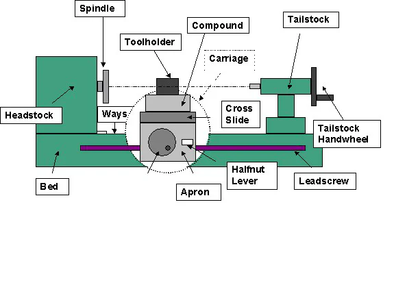
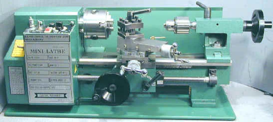
To gain a good understanding of the lathe, you will need to know the names of the various components, as illustrated below.
The carriage, in the circled area, consists of the apron, the vertical casting on which the carriage handwheel is mounted, and the saddle (not shown), the H-shaped casting that rides on the ways to which the apron is attached.


Lathe Dimensions
When comparing the size and working capacities of metal lathes there are several key dimensions to consider:
| Specification | Description |
|---|---|
| Swing over bed | The diameter of the largest workpiece that can be rotated on the spindle without hitting the bed. This is the first of the two numbers used to describe the size of a metal lathe. In the case of the 7x10 or 7x12 lathes, it is 7". |
| Distance between centers | The longest piece of work that can be held between a center in the headstock and a center in the tailstock. (See glossary below for more information.) This is the second of the two numbers used to describe the lathe size. Based on this, you would expect that a 7x10 would accommodate 10" between centers, a 7x12, 12", and a 7x14, 14". However, due to wishful marketing, the 7x10 is really only a 7x8. The 7x12 and 7x14 are what you would expect them to be. |
| Swing over the carriage | The diameter of the largest workpiece that can rotate over the carriage without hitting it. On the 7x lathes, this is about 4". |
| Diameter of spindle through-hole | The diameter of the hole that passes through the spindle. On the 7x lathes (or any lathe having a #3 Morse Taper spindle), it is about 3/4". When facing relatively long stock, the free end of the stock can pass through the spindle if it is no larger than the through-hole diameter. |
Lathe Dimensions
Here’s a table summarizing some of the dimensions for a 7x12 and 9x20 lathe:
| 7x12 | 9x20 | |
|---|---|---|
| Swing over bed | 7" | 9" |
| Distance between centers | 12" | 20" |
| Swing over carriage | 4" | 5" |
| Spindle Taper | #3MT | #3MT |
| Spindle through-hole diameter | 3/4" | 3/4" |
| Tailstock taper | #2MT | #2MT |
Glossary of Lathe and Mill Terms
| Term | Definition |
|---|---|
| Apron | Front part of the carriage assembly on which the carriage handwheel is mounted. |
| Bed | Main supporting casting running the length of the lathe. |
| Between Centers | 1. A method of holding a workpiece by mounting it between a center in the #Headstock spindle and a center in the #Tailstock spindle. The workpiece is gripped and driven by a dog. |
| 2. A dimension representing the maximum length of a workpiece that can be turned between centers. E.g., a 7x10 lathe is 10" between centers; a 7x12 lathe is 12" between centers. | |
| Bit | A sharpened cutting tool, such as a drill bit or lathe bit, used to remove metal or other material from a workpiece. |
| Carbide | An extremely hard, heat- and wear-resistant material used for making cutting tools. Usually refers to tungsten carbide. |
| Carriage | Assembly that moves the toolpost and cutting tool along the ways. |
| Carriage Handwheel | A wheel with a handle used to move the carriage by hand by means of a rack and pinion drive. |
| Carriage Lock | A mechanism for locking the carriage to the ways so that the saddle does not move along the ways during facing operations. Easy to add to mini lathes. |
| Casting | A metal component formed by pouring molten metal into a mold of the desired shape. Components are machined for precision mating surfaces like the ways. |
| Center | A precision ground tapered cylinder with a 60º pointed tip and a Morse Taper shaft, used to support a workpiece. May be live (with bearings) or dead (no bearings). |
| Center Drill | 1. A short, stubby drill used to form a pilot hole and a countersunk hole for mounting a workpiece on a center. 2. The process of drilling with a center drill. |
| Centerline | An imaginary line extending from the center of the spindle through the center of the tailstock ram, representing the lathe’s central axis. |
| Chuck | A clamping device for holding work in the lathe or drills in the tailstock. |
| Compound | A movable platform on which the toolpost is mounted; can be set at an angle to the workpiece. |
| Compound Handwheel | A wheel with a handle used to move the compound slide in and out. Also known as the compound feed. |
| Counterbore | 1. A shallow, flat-bottomed hole drilled around a smaller hole to allow a screw head to sit below the surface. 2. A hole created by this process. |
| Countersink | 1. A cone-shaped hole surrounding a smaller hole, often used for flat-head screws. 2. A cutting tool for creating such a hole. |
| Cross Feed | A handwheel or crank that moves the cross-slide via a screw. |
| Cross Slide | A platform that moves perpendicular to the lathe axis, controlled by the cross-slide handwheel. |
| Cutting Tool | The tool that removes material from the workpiece, such as a drill, reamer, or lathe bit. |
| Dead Center | A lathe center made of solid steel with no bearings, requiring lubrication during use. |
| Dog | A lathe dog or dogleg, an adapter used to clamp and apply rotational force to a workpiece mounted between centers. |
| Dovetail | A sliding surface ensuring linear motion with minimal side-to-side motion. Common in cross-slide designs. |
| Faceplate | A flat plate mounted on the spindle for holding irregularly shaped workpieces. |
| Facing | A lathe operation to create a smooth, perpendicular surface on the end of a workpiece. |
| Gib | A strip used to adjust the tightness of a dovetail slide. |
| Halfnut | A nut in two halves that clamps around the leadscrew to move the carriage under power. |
| Handwheel | A wheel turned by hand to move lathe components, often with a handle for easier turning. |
| Headstock | Main casting on the left end of the bed, housing the spindle and speed gears. |
| Leadscrew | A precision screw running the length of the bed, driving the carriage for turning or threading. |
| Live Center | A center with bearings that allow the tip to rotate with the workpiece, reducing friction. |
| Tailstock | A movable casting on the right end of the lathe for supporting long work or holding a drill chuck. |
| Toolpost | A holding device for the cutting tool, mounted on the compound. |
| Turning | A lathe operation to reduce the outside diameter of a workpiece. |
| Ways | Precision ground surfaces along the top of the bed on which the saddle rides. |
| Work or Workpiece | Material held in the lathe for machining, typically a rod or cylinder of metal or plastic. |