Review: Sieg C4 Lathe
What would the ideal hobbyist lathe be like? Some things I’d like to see…
- Bigger and heavier than the 7x12
- Variable speed motor controller
- Able to turn 5" stock without bogging down
Well, those would be nice features, but suppose we also threw in…
- Chip shield for the leadscrew
- Digital tachometer and speed controls
- Cam-lock tailstock
Then we’d be looking at a pretty nice machine. Since we’re just daydreaming, what if we also added….
- A powerful 1000W DC reversible motor with awesome torque
- Super fine power feed for a smooth finish
- Steel gears for thread cutting
- Power cross-feed!
- An optional milling head mounted to the lathe bed
What if you woke up and found that it wasn’t a daydream at all, but that it was sitting on your bench. Well, that’s what happened to me.
Next, we’ll take a closer look at what makes this such a great lathe. ~~But first, the bad news: you can’t buy one in U.S. - at least not yet, since distributors have not been established.
08/10/08 Travers Tool is a US distributor.
01/04/12 LittleMachineShop.com is a US distributor.
It is, however, available in the U.K, and probably in some other countries as well, and I would expect to see U.S distributors within the next year.
Note: some time in 2010, Sieg changed the designation of this lathe from C4 to SC4. This was done for consistency across their product line: products with the “S” prefix have the brushless DC motor which has much greater torque than the previous motors.
Sieg Lathes, Mills and Combo Machines
The unit I received from Sieg actually is designated as the M4 Multipurpose Machine. If you visit Sieg’s web site, currently (9/16/07) you won’t see this machine listed. There is an M1, which is the C1 lathe combined with the X1 mill; an M2 which is the C6 lathe combined with the X2 mill, but no M4. I’m assuming that’s because this is a fairly new product introduction.
In any case, Sieg has developed a flexible product strategy in which they have a whole range of machines to choose from - starting with the very small C1 “micro-lathe”, all the way up to the C6 benchtop lathe.
On the mill side, you can choose from the X1, X2, X3 or Super X3. If you want a “combo” lathe/mill (sometimes referred to as a 3-in-1 machine: lathe, mill, drill) you can choose from the M1, M2 or M4. Makes me wonder if an M3 model will fill in the gap sometime in the future.
For even more versatility, it was suggested to me by a reader that you could buy, for example, the M2 multifunction machine (C6 lathe + X2 mini-mill), then later buy the base and table for the X2 separately from LittleMachineShop.com to convert the X2 to a self-standing mill.
With the option to sell machines on eBay, it is easy to start small and upgrade as finances allow. As a case in point, you might later decide to sell the X2 mill and move up to the X3 or Super X3.
In this article, I’ll be looking only at the SC4 lathe without the X1 mill. A later review will cover the X1 mill attached to the SC4 to make the M4 multipurpose machine.
I don’t know this for a fact, but I would expect that there are some minor differences in configuration of the lathe, depending on whether you buy just the SC4 lathe or the M4 lathe/mill combination.
One obvious example is that the chip shield on the M4 is set back about a foot from the lathe bed to leave space for the milling head attachment. While the M4 has a slotted cross-slide table, for mounting a milling vise, I suspect that the stand-alone SC4 lathe does not.
So keep those differences in mind if you are considering the stand-alone SC4 lathe.
General Construction
Like all of the Sieg products I have used, this one is well-made, starting with a heavy cast-iron base, on up through some sophisticated digital electronics for controlling the motor.
The fit and finish is very good right out of the box. If my experience was typical, you could have this machine up and running within an hour or two after removing it from the shipping crate.
As for capacity, the specifications sheet mounted on the front of the gear train cover tells much of the story. Translated to inches, we get the following:
| mm | inches | |
|---|---|---|
| Max. Swing Over Bed | 210 | 8 1/4 |
| Max. Length of Workpiece | 450 | 17 3/4 |
| Spindle Bore | 20 | 0.79 |
| Diameter of Chuck | 100 | 4" approx. |
So this is roughly an 8x17. Strictly speaking, the length of the lathe is the distance between the tips of two dead centers; one mounted in the headstock and the other mounted in the tailstock.
Using this criterion with the centers that came with the lathe, I measured 16" between centers. With the chuck in place, a 16" long workpiece is about the maximum you can turn.
Let’s compare this lathe with the C2 and C6
| Dimension | C2 7x12 | SC4 8x17 | C6 10x22 |
|---|---|---|---|
| Swing over bed | 7" | 8" | 10" |
| Swing over cross-slide | 4" | 4 1/2" | 5 3/4" |
| Distance between centers | 12" | 17" | 22" |
| Standard chuck | 3" | 4" | 5" |
| Maximum chuck | 5" | 6" | 8" |
| Headstock Taper | MT #3 | MT #3 | MT #3 |
| Tailstock Taper | MT #2 | MT #2 | MT #2 |
| Spindle through-hole diameter | ~3/4" | ~3/4" | ~3/4" |
| Weight | 80 lbs. | 207 lbs. | 320 lbs. |
As on the smaller mini-lathe (C2) and the larger C6 10x22, the headstock has a #3 Morse Taper (MT) and the tailstock a #2. I’d like to see a larger through-hole, especially on the C6, but that will have to wait for some future model.
Note that a common modification, first implemented by Varmint Al on the 7x10 mini-lathe, is to ream out the through hole to 13/16" (0.8125"). It’s not much of a gain, but it can make a difference if you have a piece of 3/4" diameter stock that is just a little oversize.

Bed Construction
Heavily braced by cross-ribs, the bed casting is a solid, heavy piece of cast iron. Four bolt holes are provided for bolting the lathe down to a bench, but is was sufficiently heavy that I felt confident taking light cuts for testing without bolting it down.
For safety during regular use, of course, I highly recommend bolting the lathe to a strong, sturdy workbench. There are many opinions about the best way to do so without the potential of creating stress that may twist the bed, so you may want to do some web searches to get some ideas on how to go about it.
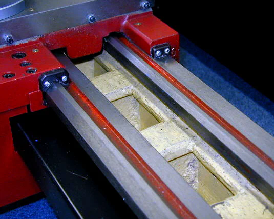 Lathe bed cross-braces
The ways are of a dual-prismatic design, which is to say, they have two raised areas with a prism-shaped cross section extending the length of the ways.
The front prism guides the carriage; the rear prism guides the tailstock. The prisms provide a precision-ground guide surface to ensure that these components track exactly parallel to the lathe centerline.
A quick, unscientific test with a center punch indicates that the ways are not hardened, so you will need to be extra-careful not to drop the chuck or tools on the ways, or you may end up with a ding or dent that will need to be smoothed out with an India stone.
 Bed cross-section
The threaded hole at the end of the bed is for a cap-head screw that prevents the tailstock from accidentally being slid off the end of the ways. On the mini-lathe, space is at such a premium that I routinely remove the tailstock, when it is not in use, and store it on a special stand I made for that purpose.
On this lathe, there’s enough room that the tailstock is out of the way when resting at the end of the ways.
A large, heavy-gauge sheet metal chip shield extends from the front of the headstock to the end of the bed. On this M4 model lathe/mill combo, the shield is set back about a foot to accommodate the milling head which normally is mounted on the back side of the lathe bed.
 Set-back chip shield
Spindle and Chuck
The spindle is similar in appearance to the one on the mini-lathe, only 4" diameter rather than 3". Two sets of mounting holes are provided to accommodate both 3-jaw and 4-jaw chucks.
As you may have seen in some of my other articles, it usually is possible, and often desirable, to use a chuck larger in diameter than the spindle. This can be done by making or buying a back plate to adapt the larger diameter chuck to the spindle.
 SC4 spindle and chuck mounting holes
On the newer Sieg lathes, including this one, this process is somewhat complicated by the polycarbonate safety shield mounted above the chuck. Although it helps to keep chips from flying around, the main function of the safety shield is to ensure that the lathe can’t accidentally be started with the chuck key in the chuck.
When in the raised position, the shield activates a micro-switch that prevents the motor from starting. In fact, if you raise the safety shield while the motor is on, the motor quickly comes to a stop and can’t be restarted until the shield is returned to the lowered position.
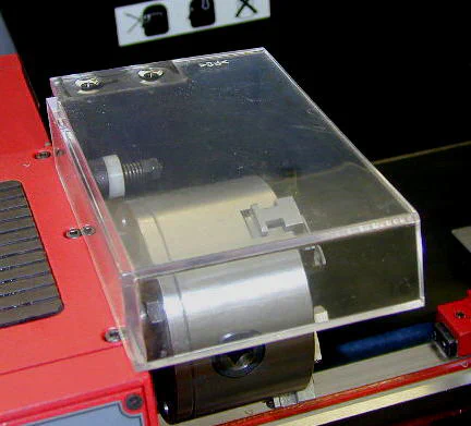 Safety shield in lowered position
Another safety feature, one that I haven’t seen before, is the spring-eject feature on the chuck key. Forgetting to remove the chuck key from the chuck before starting the lathe, can fling the chuck key across the room, possibly striking the lathe operator, a visitor, or something breakable, like a shop microscope.
You know how Murphy’s law works!
 Chuck key with red handles and ejector spring
On this chuck key, you must press inwards to keep it engaged with the chuck - as soon as you release it, it pops out of the chuck, pretty much eliminating the possibility of leaving it in place accidentally.
Together with the chuck safety shield, and the red handle covers, this feature significantly improves the safety of operating the lathe.
Runout
One thing that really impressed me was the spindle runout, also known as TIR (Total Indicated Runout). This was measured by mounting a dial test indicator (DTI) so that the probe contacts the inner surface of the spindle taper.
After I adjusted the probe tip, I slowly rotated the spindle by hand, but observed no movement of the DTI needle. Double checking to make sure that the probe was, in fact, contacting the spindle, I repeated the test.
Same result. Then I realized it: the needle was in fact deflecting a tiny amount.
Now this is a good-quality Peacock brand DTI, with divisions of one-ten-thousandths of an inch (.0001"). If what I was seeing was true, the runout was well under one-ten-thousandth - on the order of two hundredths (0.00002") as nearly as I could estimate by the tiny motion of the needle.
Wow, I hope that’s true because, if it is, it is exceptionally good for a lathe intended for hobby use. Naturally, the runout will vary from machine to machine, so I wouldn’t necessarily expect that every SC4 lathe would be this precise, but we won’t know until we get more results from other owners.
 Measuring runout of the spindle
TIR is important because it determines the most accurate cut that the lathe can make. Essentially, it is a measure of any “wobble” or play, in the spindle and spindle bearings. If you are trying to turn a workpiece to a diameter of .5000", but the runout is .001" (one one-thousandth), you just won’t be able to do it. As a point of comparison, on the less expensive mini-lathes, I have typically measured about 0.0003 - 0.0004" TIR.
Standard Chuck
The standard 4" 3-jaw chuck, supplied with the lathe, is similar in appearance to the ones on the mini-lathe. It looks well-made and works smoothly out of the box. As a rule, chucks tend to get smoother over time as they wear in. As expected, a separate set of outside jaws is included.
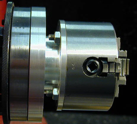 Standard 4" 3-jaw chuck
Mounting the chuck is a little different than on the mini-lathe. On this lathe, hex-head bolts were provided and are inserted from the rear of the spindle plate into the threaded holes on the back of the chuck. Then they are tightened down using a 14mm wrench.
A slight disadvantage to this approach is that it is not always immediately obvious, when looking at the back side of the spindle plate, which of the 7 holes are the correct ones - i.e. the ones that match up with the chuck. Also, if the chuck is rotated slightly so that the holes don’t match up, it can be tricky to get the first bolt started.
It would be a simple matter, of course, to buy or make some studs and convert to the same approach used on the mini-lathe, which I probably will do.
Note (12/10/07) I made some index marks on the outer diameter of the spindle plate and corresponding marks on the chuck. This solved the problem of matching up the holes.
The space between the back of the spindle plate and the headstock is 3/4" on the SC4, compared to 1/2" on the mini-lathe.
This relatively generous space makes it easier to manipulate the mounting bolts (or nuts, if you go that route). Even so, it is necessary to tilt the bolts to get them into the hole, as they are slightly longer than 3/4" inch from the top of the hex head to the tip.
 Chuck mounting bolt
My 4" 4-jaw chuck, originally purchased for use with a backing plate on the mini-lathe, fit directly onto the SC4 spindle.
 4" 4-jaw chuck (not included) mounted on spindle
Motor and Electronics
This is one area where the SC4 departs significantly from both the C2 mini-lathe and the C6 10x22. The mini-lathe has a variable speed motor control, but no digital controls or RPM readout.
The C6 uses a fixed-speed, reversible AC motor: all speed changes are made by stopping the motor and moving a drive belt to various combinations of pulleys.
By comparison, the SC4 is a really slick setup.
First of all, the motor is a nice-looking unit rated at 1000 Watts DC. It’s mounted on the back side of the lathe behind the headstock and, with its integral cooling fins, looks very high-tech compared to the motor on the mini-lathe.
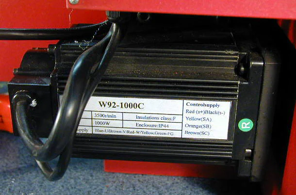 1000 Watt DC motor
I don’t have the expertise to determine if the rating is truly 1000 W, nor do I really care as long as the motor meets my machining needs. Using my hands as a sort of human Prony brake, I was unable to stop the rotation of the chuck at the minimum speed of 100 RPM.
I don’t recommend trying this at home. OK so I warned you. In any case, by contrast, it is fairly easy to stop the rotation of the mini-lathe using the same approach, even though the smaller 3" dia. chuck reduces the torque that you can apply.
What does that mean in practical terms? Well, I haven’t done enough testing yet to be sure, but the mini-lathe has an unfortunate tendency to bog down and stop when you work on stock greater than about 3" in diameter.
Although I haven’t tested that tendency on the SC4 yet, I’m expecting that it will do much better.
Last weekend I turned a 6" diameter x 1/4" aluminum disk as a replacement for my disk sander. The SC4 handled this operation with ease.
As the tool bit dug into the edge of the disk, you could hear a momentary slowdown. Within a few milliseconds, the electronic feedback had increased power to bring the motor back to the speed set on the digital tachometer.
For a lathe in this size class, the torque was awesome. This job, which probably would have taken an hour on the 7x12 mini-lathe, was completed in a few minutes.
Electronics
As you would expect on a lathe with digital controls, the electronics are more complex than on the 7x lathes, and even more so than for the C6, which does not have electronic variable speed control.
On the SC4, the electronics are distributed between two insulated plastic boxes, one mounted in the upper-left corner of the gear housing, and the other mounted on the back side of the headstock.
The first box appears to be the DC power supply, judging from the large heat sink, row of large capacitors and bridge rectifier that are visible when the cover to the box is removed.
A small DC fan, similar to those found in computer power supplies, provides air flow.
 Power supply box in change gear area
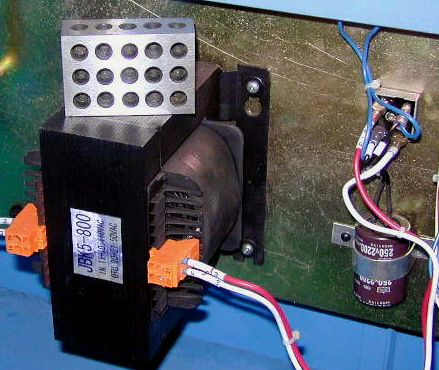 A look inside the box
Mounted behind the headstock, we find the second electronics box. The AC outlet is where the milling head plugs in.
 Second power supply box
 Internals of 2nd box
The second control box deals with the digital display and speed control. A short section of PVC pipe runs through the headstock, serving as a wiring tunnel between this box and the control box on the front of the lathe.
Control Panel
One look at the control panel tells you that this is a machine in a different class. It reminds me of the controls on the Super X3 mill, which use a similar digital readout and control panel.
But this one is even better, with a large-format LCD digital display and raised membrane buttons that provide tactile click feedback when pressed.
Plus, it just looks cool. Women, formerly bored by your machines, now will take notice. Just don’t make the mistake I made and try to explain how it works.
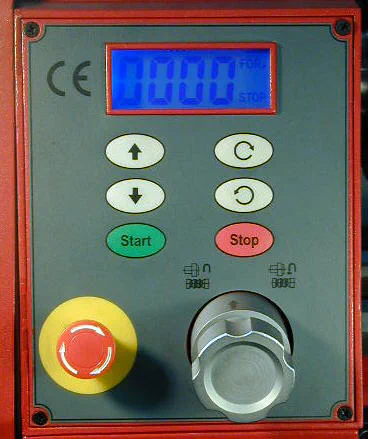 SC4 Control Panel
Mounted down below are the main power switch, fuse holder and pilot light.

Digital Display
When you toggle on the power, a short beep signals startup and within a second or two, the digital display glows a nice nuclear blue color (See Cerenkov radiation). Even if your eyes are a bit weaker than when you were young, you should have no trouble reading the display.
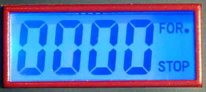
 How they make that cool blue color (just kidding!)
Motor Control Buttons
On the top right corner of the display, FOR (Forward) is shown, indicating that the lathe spindle is set to rotate in the forward (counterclockwise) direction.
Press the green Start button and the speed ramps up until it reaches 100 RPM, then holds there, steady as a rock. Press the Up-arrow button momentarily and the speed increases to 110 RPM.
Each press of the Up-arrow increases the speed by 10 RPM. Holding it down quickly accelerates the lathe to higher speeds, which you can monitor on the digital display.
Release the button and the lathe quickly locks into the last speed displayed. Same for the Down-arrow button.
 Tactile membrane control buttons
Press the red Stop button and the lathe quickly decelerates to a stop; so quickly, in fact, that I suspect that a technique known as back EMF (Electro Motive Force) is employed for dynamic braking.
Back EMF uses the electromagnetic field built up in the motor coil to quickly stop the motor. Using a digital stopwatch, I measured 1.00-1.04 seconds to come to a complete stop from 1000 RPM.
Auto-Reverse Feature
Another interesting feature, that takes advantage of the dynamic braking, is automatic reversing of the motor direction. If you press the Reverse button while the motor is running in the Forward direction, the motor quickly brakes to a full stop, reverses direction, and accelerates back to the same RPM setting.
This will no doubt prove to be a handy feature for milling operations, where you just want to reverse the direction of carriage motion, but it could also be convenient when tapping threads.
After the motor has been stopped using the red Stop button, pressing the green Start button will accelerate the motor back to the speed at which it was last running when stopped.
This is convenient when repeating a series of similar operations such as stopping the lathe to measure the workpiece diameter, then restarting it. However, it could come as a surprise if you take a lunch break, then come back and punch the Start button.
If you’re not sure what speed you left it set at, and don’t want to be surprised, you can simply press the yellow Emergency Stop button, then reset it to reset the motor to 100 RPM (or power the lathe off, then back on).
Emergency Stop Button
 Emergency stop button (with locking feature)
The Emergency Stop button, which, in one form or another, has been standard equipment on all Sieg power tools for the last few years, provides a quick way to shut down the machine in emergency, like, let’s say, when you run the cutting tool into the chuck! Naturally, with my years of experience, I no longer make such amateurish mistakes.
Well, except maybe that time when I ran the C6 carriage into the chuck a while back. Damn tough machine. Nothing broke.
That being said, the Emergency Stop has its uses. It not only stops the machine, but stays mechanically locked in the off position until you turn it clockwise a quarter turn to unlock it.
Then the lathe is back in a neutral state, ready to start by pressing the Start button. If you press the Start button while the Emergency Stop button is still in the Off position, nothing happens.
You can also use it to reset the machine back to 100 RPM - the default at power up.
To run the spindle in reverse (clockwise), just press the button with the clockwise arrow.
Spindle Engagement Control
Okay, so what about that big metal knob to the right of the Emergency Stop button? When I first looked at it, and studied the little hieroglyphics that accompany it, my conclusion was that it reverses the leadscrew, relative to the spindle, for cutting left-hand threads.
Wrong. What it actually does is decouple the spindle drive from the motor while leaving the leadscrew engaged.
 Spindle engage/disengage control knob
Why would you want to do that, you ask? Well, remember, this machine is designed to work in concert with the X1 milling head. When doing milling operations, you don’t need (and, if you think about it, don’t really want) the chuck spinning while you’re trying to do milling.
So, just disengage the spindle and away you go.
 Spindle engagement gear
A look inside the headstock reveals the gear mechanism that makes this feature work. When you turn the knob, a linkage slides a gear to the left or right along a splined shaft, engaging or disengaging with another gear on the spindle shaft.
Cam-lock Tailstock
 Tailstock front view
For many mini-lathe owners, including myself, the Cam-lock tailstock modification was the Holy Grail. Why? Because the tailstock is used so frequently in drilling and reaming operations, that loosening and retightening the lock nut every time you need to move it is a colossal pain.
Of all the mods I’ve made on my 7x12 mini-lathe, I consider the cam-lock tailstock to be the most beneficial, along with the carriage lock.
 Cam lock tailstock (viewed from rear of lathe)
So now, on the SC4, it is provided as a stock feature. And it’s nicely done, too. The locking lever is mounted at the rear of the tailstock and rotates towards the operator to lock the tailstock.
The camming action is smooth and strong, ensuring a gorilla-tight lock with little force applied to the handle. Unlocking is just as smooth and easy. You can easily adjust the locking point by tightening or loosening a Nylock-type nut on the bottom side of the tailstock assembly.
As on all of the Sieg lathes I’ve seen, the tailstock on this one provides for lateral displacement for cutting long tapers. I’ve never actually had an occasion to use this feature, but the idea is to mount the workpiece between centers, using a dog) to drive the workpiece, and offset the tailstock to produce a tapered cut.
I was a little surprised to find that the tailstock handwheel does not include a calibrated gauge as the one on the C6 does. On the other hand, the tailstock barrel on the SC4 is calibrated in both inches and mm, while the one on the C6 is not.
For most drilling operations the depth is not critical, so this is only a minor issue.
I have heard reports that the tailstock handwheel now has a calibrated collar.
End of update
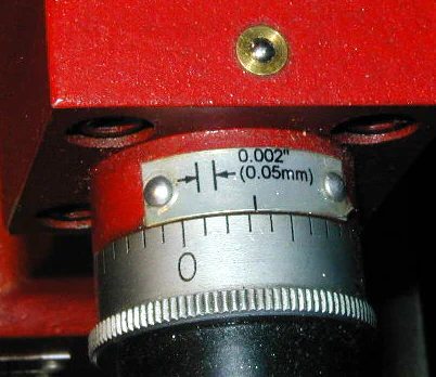 Uncalibrated tailstock handwheel
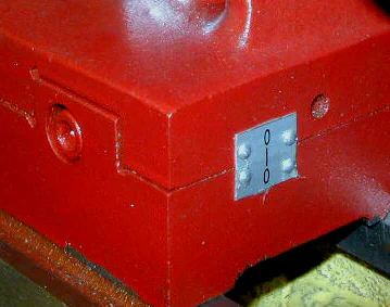 Calibrated tailstock barrel
Headstock
Inlaid into the top surface of the headstock is a nice ribbed rubber tool mat. I suspect that many lathe users find this area to be a convenient spot to lay down wrenches and chuck keys.
The rubber mat keeps this surface from getting dinged and scratched by the tools, while deadening the sound of placing tools there. I, on the other hand, depend on that same surface for mounting magnetic base dial indicators, and am already missing the option of using it that way.
So, I guess I’ll find a new place for them. Anyway, it’s not a big deal for me, and may be a plus for other owners.
 Tool pad on top of headstock (with oil port)
Carriage, Cross-slide & Compound
Massive. That’s how the carriage first impressed me. For the size of the lathe, it is a heavy, formidable chunk of cast iron.
 Carriage, cross-slide and compound
We like that. Why? Because mass reduces vibration and thus increases precision. Massive components on a lathe make it more precise. Mass is our friend.
Vibration is not. So, start out with good quality spindle bearings to give a low TIR, then add a massive bed and a massive carriage. These are the makings of a lathe than can do accurate work.
Carriage
If you’re not familiar with metal lathes, the carriage is the cast iron assembly that moves along the length of the lathe bed, riding on the ways.
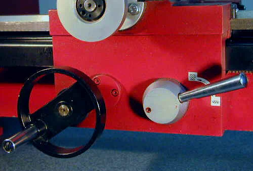
It can be moved by hand, using the large black handwheel in the lower left corner of the photo, or driven by the lathe motor by engaging the power feed lever to the right of the handwheel.
A cap screw, operated with a 4.5mm hex wrench, locks the carriage to the ways for operations such as facing. As I did on the C6 lathe, I will no doubt soon make a dedicated screw and handle for this function, as I use it frequently.
Made of heavy cast iron, the carriage handwheel adds a flywheel effect when you want to move the carriage quickly. Pulling outwards on the handwheel disengages it so that it does not rotate when the carriage is driven under power feed.
This is both a convenience and a safety feature.
Just to right of the handwheel is the power feed lever, also referred to as the “half-nut” lever. This odd name derives from the function of the lever in engaging and disengaging two “half-nuts”; i.
e. two sides of a nut, with the threaded leadscrew. On this lathe, the leadscrew is not visible from above, because it is covered by the black sheet metal chip shield that runs the full length of the bed.
The chip shield prevents the annoying accumulation of chips in the leadscrew threads - a phenomenon all too familiar to users of the mini-lathe, which has an exposed leadscrew.
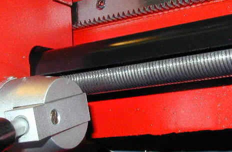 View of the leadscrew from below
Another feature that should bring special joy to mini-lathe users, is that the electronics are mounted on the back of the headstock - well protected from flying metal chips.
On the mini-lathe, the lead screw passes through the enclosure that houses the electronics, and has a tendency to carry metal chips right in there where you don’t want them.
Half-Nut Lever
 Half-nut lever
The leadscrew is engaged with the lathe spindle by a series of gears mounted on the left end of the lathe. By selecting various combinations of gears, screw threads can be cut to a desired metric or inch thread.
For example, to cut a 1/4-20 thread, with a 1/4" diameter and 20 threads per inch (TPI), you look at the chart on the top of the gear train cover to determine the gears needed for that thread pitch.
Thread cutting is a fairly complex topic, so I won’t go into a lot of detail here, but will say a little more about it when I describe the gear train later in this article.
Power Feed Transfer Lever
Mounted on the right hand side of the carriage, is the power feed transfer lever. In the “up” position, power feed from the leadscrew engages the cross-slide drive, moving the cross-slide in or out, depending on which direction the spindle is rotating.
In the “down” position, power feed drives the carriage along the ways, much as the half-nut lever does, but at a lower speed. In the middle position, marked “0”, the drive is in neutral.
A spring-loaded locking feature prevents the handle from accidentally being moved into the cross-feed position; to engage the power cross-feed you must press the lever to the left while shifting it upwards.
As anyone who has tried to face a disk 5" or more in diameter knows, your wrist cramps up from the repeated cranking of the cross slide in and out. Not only that, but after the first 5 passes, boredom sets in.
Power cross-feed is a great feature. Of course, on this machine, the power feed does double-duty, since it also provides power feed for milling operations when using the milling head on the M4 combo-machine.
 Power transfer lever
Cross-slide, Compound and Toolpost
This version of the SC4 lathe, configured as the M4 lathe/mill combo, has slots that run the length of the cross-slide. Four T-bolts are used in these slots to attach the compound.
Judging from the appearance of the mount, and the little cutting work I’ve done so far, the compound seems to be firmly anchored to the cross-slide. I mention this only because that is a weak area in the design of the otherwise popular 9x20 lathes.
 Cross-slide, compound and toolpost
During milling operations, the compound normally would be removed and replaced by a milling vise or a workpiece clamped to the cross-slide.
The compound also has slots, so you could mount a small milling vise or workpiece to the compound to make milling cuts at a compound angle, although that could also be accomplished by mounting the vise or workpiece to the cross-slide at an angle, or using a rotating vise.
Due to the cross-slide slots, you can mount the compound anywhere along the top of the cross-slide. This feature provides flexibility when working with large or odd-shaped work.
Chrome handles, similar to those on the mini-lathe, provide control for manipulating the cross-slide and compound. If you aren’t familiar with them, the shape of these handles enables the operator to rapidly move the cross-slide by grasping the narrow section, while providing for precise control by grasping the balls at opposite ends of the crosspiece.
On the mini-lathe, these handles are so small that the operator’s knuckles constantly get knocked by the retaining nut. On this lathe, the handles are large enough that that does not happen - even with my beefy hands and stubby fingers.
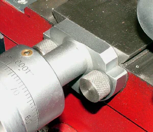 Cross-slide handle and dial
Difficult to photograph, due to its location, the cross-slide nut is split and has two small set screws to allow for backlash compensation. Here’s a photograph taken with a small mirror that will give you the general idea.
The compound nut has a similar arrangement.

Compound
Mounted atop of the cross-slide, the compound can be rotated and locked into position to advance the cutting tool at an angle to the workpiece. This feature is used for cutting short bevels and tapers, for convenience in positioning the cutting tool and for setting the cutting tool at the correct angle for cutting screw threads.
 Compound and tool holder
On the M4 combo machine, the compound is 6 3/4" long. Two slots for T-nuts extending 6" along the compound are available for clamping work for milling operations.
Similarly, the comound is mounted to the cross-slide slots by four T-bolts. These slots may not be present on the basic SC4 lathe.
Two easily accessible socket head screws on opposite sides lock the compound in place. The angular scale is printed on a separate strip of aluminum riveted to the compound base.
The index mark for the scale is
 Protractor scale. Index mark is below 30 deg. setting.
The compound has a range of about 3 3/8" when set parallel to the ways (0 degrees); when set at 45 degrees, the motion is limited to 2 1/4" by the corner of the compound mouting plate.
On the SC4 lathe that is not part of the M4 combo machine, the range may be different. The compound handwheel is a smaller version of the one on the cross-slide, but still provides enough clearance to avoid bashing your knuckles on the retaining nut.
Crisply etched numbers on the scale make it easy to read. Underneath the compound, a brass split-nut allows for backlash take-up.
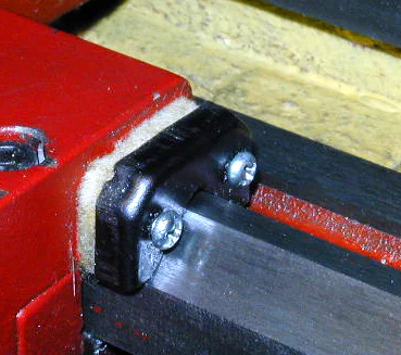 Compound handwheel
Toolpost
The stock toolpost is a larger version of the type familiar to mini-lathe owners. Serviceable and rugged, it will do the job, but you will have to use shims under your tools to adjust the height. Readers familiar with my site know that I strongly recommend replacing the stock toolpost with an adjustable Quick Change Tool Post (QCTP). I don’t know of one at this time (9/16/07) that is a direct fit for the SC4.
There may be ones out there, but I just haven’t had time to research that. Check with LittleMachineShop.com if you need advice.
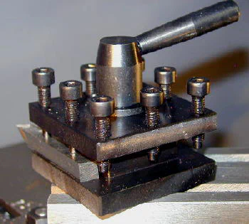 Stock 4-sided tool post
Drive Train
Located behind the hinged door on the left side of the headstock is the change gear train. Most of the time, the gears are set for driving the carriage and cross-slide for power feed cutting operations.
When the need arises to cut threads, gears are selected according to the chart on top of the access door and are installed in the proper location in the gear train to cut the desired thread pitch.
 Gear train for thread and feed selection
 Gear setups for metric threads
 Gear setups for inch threads
 Gear setups for power feed
Unlike the 7x lathes and the C6, on this one, the lead screw appears to be metric, with conversions done by the gear train to produce inch (SAE) threads.
A wide range of both metric and inch threads can be cut using the change gears provided. I would assume, that as on the 7x lathes, additional thread pitches other than those shown in the table can be cut with the provided gears.
This lathe includes the mythical 127 tooth gear, much sought after but rarely obtained by mini-lathe owners. What’s so special about a 127 tooth gear?
Well, since the conversion factor from centimeters to inches is 2.54 exactly, and 127 is 254/2, the 127 tooth gear provides an exact conversion ratio for cutting metric threads on a lathe equipped with a leadscrew having inch units, or vice-versa, in this case.
Although it was not apparent to me when I first wrote this review, some C4 owners advised me that both left- and right-hand threads can be cut on the C4. The trick is to move the spindle drive gear to the outer position. Here’s a link to a site where that’s explained and illustrated.
Conclusion
I really like this lathe. It’s a good size for home shop use: not too big, not too small, and is accurate and well-made. Many of the quirky features and limitations of the mini-lathe have been improved in this design, while new features, such as the digital speed control, digital readout, power cross-feed and cam-lock tailstock make it efficient and fun to use.
Adjustable nuts on both the cross-slide and the compound reduce backlash to close to zero, giving a feel of accuracy and positive control during machining operations.
Even the covered leadscrew, though it may seem like a small matter, eliminates the need to constantly brush metal chips from leadscrew threads - a common exercise on the mini-lathe.
Don’t misunderstand me though: the mini-lathe was and is a great way to get started at a price that makes it possible to do so. But if you find that you like machining and plan to do it for a few years or more, you can’t go wrong moving up the SC4 lathe.
Plus, as I mentioned earlier, you can probably sell your mini-lathe on eBay and recoup a good percentage of what you paid for it.
08/10/08 Travers Tool is a US distributor.
01/04/12 LittleMachineShop.com is a US distributor.
Those lucky chaps in the U.K, however, can order them off of eBay. As for other parts of the world, I have no information on the availability at this time.
(12/18/10) Jaakko Fagerlund in Finland sent me a nice email about his SC4 purchase. Here’s a link to his web site.
(08/02/11) Gabor Benyhe in Hungary also has some good information on the SC4.