Sieg X3 Power Feed
A while back, when I was working on the review of the Super X3 mill, Jack Mogren of Walden Specialties contacted me about the power feed for the X3 and Super X3 mills.
Jack has had some success in importing the power feeds, as well as other machine tool accessories, and selling them on eBay.
Jack admitted to me that this is not a “get rich quick” formula, by any means, but for someone who has the patience and inclinations to decipher the sometimes arcane procedures for importing from China, there is a small business opportunity.
(Update 4/21/07: Walden Specialties is no longer selling these power feeds; they are available from LMS)
I’d been hoping to try out the X3 power feed, so I was quick to agree to do a product review.
Even on the little mini-mill, with a table length of 15", running the table back and forth by hand when working on a relatively long work piece can quickly become tiresome, so I built myself a power feed for that machine a few years back, and it continues to serve me well.
On the X3 mill, with a 21 1/2" table length, a power feed is even more desirable.
Installing the Motor and Controller
Jack has put together a handy installation guide, which, together with a few common tools, is all you need to get the job done.
Installation is pretty quick and easy and should take about 60-90 minutes. After removing the cover from the power feed, you bolt the mounting plate to the end of the mill table, then replace the cover.
Next you mount the limit switch to the front of the mill, install the two adjustable limit triggers, and you’re ready to go. Most of the time is actually spent mounting the limit switch.
The first step is to remove the plastic cap on the left table end plate. You may be able to twist it off by hand, but I found that I needed to use a wood chisel to pry it off.
To those of you who may be woodworkers, and shocked by such blatant tool abuse, trust me - this was a very old chisel reserved for just such chores.

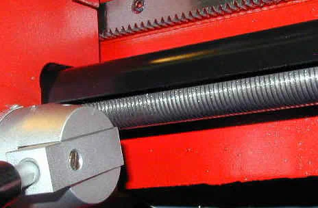
Removing end-cap to expose lead screw
Next, remove the four Phillips head screws from the right end of the power feed housing.

Remove the 4 screws that hold the motor plate in place
Tilt the housing so that the end-plate is downward and gently tap the housing with the palm of your hand - the end-plate and motor assembly should slide out from the housing.

Motor mounting plate removed from housing
The brass bushing on the face of the motor mounting plate engages with the hole in the table end plate - or at least it is intended to. I found that I had to first scrape the black paint off of the inner edges of the mounting hole in order for the bushing to fit.
I used small wood chisel (again, I apologize!) for this purpose. Even after removing the paint, the bushing is a snug fit into the hole.


Removing paint from inner surface of hole
One more thing to watch out for: the small alignment pins on the upper corners of the table end-plate may interfere with the flush mounting of the motor plate.
Jack drilled shallow holes in the motor plate to accommodate the pins; I simply tapped the pins with a brass hammer until they were flush with the table end-plate.

Tapping alignment pins into place
For the next step, it is a good idea to support the housing while mounting the mounting plate to the end of the mill table. This will help avoid putting excessive strain on the motor wiring.
I used a small empty shipping box for this purpose.

Motor housing supported by a box
The motor shaft terminates in a flat blade that engages with a corresponding slot in the end of the table leadscrew. Turn the table X-axis handle to align the slot with the position of the flat.
With the power feed cabinet supported, move the motor plate into position with the brass bushing mating with the hole in the table end-plate. Make sure that the part of the motor plate with the cutout is facing the front of the mill.
Also, ensure the flat on the motor shaft lines up with the recess in the leadscrew.

Mounting the motor plate on the table end-plate
You may need to twist the motor plate back and forth a little to get the brass bushing to recess into the hole. Once everything is properly lined up and engaged, insert and tighten the two cap screws, that come with the power feed, to mount the motor plate onto the table.
Due to the proximity of the cap screws to the side of the motor, you’re forced to turn the cap screws about a half-turn at a time, which tried my patience.

Bolting the motor mount to the table
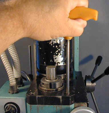
So, instead of taking the two minutes that this task would have required, being a man of little patience, I rigged up an extension to my power screwdriver and drove those screws in in about 30 secs.
Yes, it did take me 4 or 5 minutes to find the parts for the screwdriver extension, but it still made me feel good to do this job the right way!

Power screwdriver setup
Update 02/07/07
A few weeks after I performed this operation, I purchased two sets of “ball-end” hex wrenches - a metric set and and SAE set. These turned out to be just the right tool for this job, allowing me to angle the wrench away from the motor while turning it.

Using ball-end metric hex wrench for easy access
End of update
With the motor now attached to the table, slide the housing over the motor and replace the four screws. This step completes the installation of the control unit.
Next, we will mount the limit stop switch.
Installing the Limit Switch
To mount the limit switch, you must drill and tap two mounting holes in the front of the Y-Axis slide. A small white button extends from each side of the limit switch housing.
Also provided are two mechanical units that mount into the slot along the front edge of the table to trip the limit switch.
These trip units can slide back and forth along the slot and are locked into place at the point where the power feed is to be shut off.
You may find that they are a tight fit in the slot - Jack had to touch up his with a Dremel-type grinder to get them to fit. Mine were a little tight, but were OK after I lubed ’em with a little grease and worked them back and forth in the slot a few times.

Limit switch trip unit
Position the limit switch housing in its approximate location on the left front of the Y-Axis slide, then slide each of the trip units until they are close to, and on either side of, the limit switch.
Center the switch housing between the two gib screws, being careful to allow clearance on both sides for the gib screw lock nuts to turn.
Adjust the height of the limit switch to match the height of the trip units, then use a marker pen or prick punch to mark the position for the limit switch right-side mounting hole on the front of the Y-Axis slide.
You can’t mark the left-side hole at this point, because it’s behind the cable strain-relief.

Adjusting the limit switch height
After marking the position of the right hole, remove the three flat-head screws and separate the back plate from the switch housing.
In a situation like this, if you mark both holes, then drill and tap them, you sometimes find that the holes do not line up exactly with the corresponding holes in the mounting plate.
To minimize this tendency, I like to drill and tap one hole, then mount the plate with a screw before marking the position for the second hole.

Drilling the first mounting hole
While the positioning of the mounting holes is not “critical”, there’s very little clearance between the sides of the switch housing and the neighboring gib screws and lock nuts, so it pays to take some extra care in positioning the screw holes.
I used a fine-tip Sharpie marker to trace an outline of the hole, then I used a center punch to mark the center of hole. The small depression from the center punch will help to keep the drill bit centered.
It also helps to use a smaller drill to start the hole, then drill it out with the final size tap drill. Use a variable speed drill, starting at low speed and gradually increasing the speed once the drill bit gets seated into the proper location.
This will help to keep the drill bit from wandering off the punch mark.
In case you’re curious, here’s what the inside of the switch housing looks like:

Interior view of limit switch housing
When mounting the back plate, note that that one side has been milled to provide clearance for the moving table. The milled side mounts against the dovetail slide.
I did not find any mounting screws for the limit switch in the small bag of parts (or maybe I misplaced them?), so I used some 8-32 x 1/4" stainless flat-head screws that I had on hand.
I first drilled a small (3/32") pilot hole, then drilled the hole out with an 8-32 tap drill (#29) to a depth of about 5/16".
I carefully tapped the hole using an 8-32 tap with a tapered tip to start and a bottoming tap to complete the threads.
As always when tapping, liberally apply tapping fluid to avoid seizing the tap in the hole.

Tapping the first mounting hole
Work carefully and be sure to keep the tap wrench supported at all times - you really don’t want to snap off the tap in the hole! For more tips, see the Premium Content article on Tapping.

Marking the second mounting hole
Next, mount the back plate using the newly tapped hole. Now mark the location for the second hole, remove the plate, drill and tap as before. Mount the plate using both screws, then mount the switch housing onto the back plate.
One of the three screws has insulating tubing around it to avoid the prospect of a short circuit - that screw goes in the upper-center hole.

Completed limit switch installation
That completes the installation of the limit switch. Now let’s do some testing!
Controls and Operation
Let’s take a look at the controls:

- Left - Neutral - Right Control Lever - Controls the direction of table movement
- Feeding Speed - Sets table movement speed; resets controller
- Fault light - Indicates overload or “not-ready” condition
- Power - Glows green when power is on
- Fuse - Fuse housing
- Quick Moving - When held depressed, moves the table at a rapid rate
The motor control unit is powered on by plugging it into a 120V AC outlet - surprisingly, it does not have a power on/off switch. While it’s not a major problem to add one, it seems odd that one is not included.
Oh well. Jack added an inline switch to his unit.
When the power cord is plugged in, the Power light glows green. The speed control knob includes a switch that resets the controller when the knob is turned fully counter-clockwise.
Any time that you start up the power feed - or reverse direction - you must turn the speed control until it clicks into the reset position.
This seemed a little awkward at first, but it is an important safety precaution: you really don’t want the table to go zipping off at full speed unexpectedly!
Also, resetting the speed to zero when reversing direction may keep the power supply from being overloaded as it might be if the direction was reversed with the speed set to maximum.
In any case, after a few minutes use, this all seems natural.
Most of the time, you will probably use the controller without the limit stops. In that case, just reset the speed to zero, set the direction lever in the direction you want the table to move, then turn on the speed control knob and advance the speed to a convenient setting.
The speed you select will depend, of course, on several factors such as the size and speed of the cutting tool, the hardness of the workpiece and the length and depth of cut.
For home shop use, it’s practical just to start out using light cuts and slow feed speeds until you get used to the flow of things. As you get a feel for how all these variables interplay, you can use higher speeds when convenient.
So, how fast does it go? To measure the speed, I mounted a Sharpie pen in the chuck and adjusted the head so that the tip of the pen marked a line along the surface of the table.
I then set the two limit stops so that the pen traced a 10" line between stops and timed how long it took for the table to make this run at full speed.
It took 25 sec. to go 10", or .40 in/sec.
That’s really a pretty good clip - too fast for most work, I would venture to say, but that’s a good thing.
I’ve found from experience, that it’s better to have too much speed (assuming of course, that you can slow it down!) than too little, since there will be times when you need to take a light cut along a long surface where the extra speed really helps.
One feature that I really like is the “Quick Moving” button - sorta like warp speed! This feature is for rapidly moving the table - especially useful during setup operations when the table needs to be positioned near one end or the other.
I didn’t measure the speed, but, trust me, it’s plenty quick.
As for power, this unit has plenty. Sieg has become proficient in developing variable speed PWM power supplies for DC permanent magnet motors and this combination provides a pretty near ideal combination of speed range combined with excellent torque.
That factor, plus the reduction gear box on the motor, provides copious torque for a mill of this size.
Another feature of the power supply is that it can detect overloads and instantly shut down the power. This is a great feature if you dig the tool in too deep, or run the power feed out to the end of the table limit.
The power feed shuts down and the Fault light comes on. You must reset the speed control to the Off setting to restart.
Well, next weekend, I hope to do some practical testing under realistic shop conditions - so check back then.
Testing
Before you start using the power feed “for real”, make sure you have enough clearance on either side of the mill. The first time I tested the power feed, I got a little over-exuberant and ran the X-axis handwheel into the back side of the chip shield on my C6 lathe.
No real harm was done, since I was able to shut off the power feed right away, but it did carve a little circle into the paint:

Make sure you have enough room!
For my first real test, I set up a piece of 1/2" aluminum plate about 10" long along the edge. The objective was to put a clean edge on the workpiece using the side of a 5/8" dia.
4-flute end mill. The end mill diameter was selected for convenience, since that was the size that I happened to have mounted in the end mill holder at the time.
I mounted the aluminum plate on a pair of 1-2-3 blocks and clamped it down with components from my clamping kit.
Then I attached a dial indicator to the head of the mill using a magnetic base and used the DI to line up the edge of the workpiece so that is was parallel with the table.
This step was not really necessary, since this was just a test, but it avoided a problem that might otherwise have occurred: If the workpiece had not been nearly parallel to the table, the end mill would have either cut deeper or shallower as it progressed along the edge, depending on which way the edge was slanted to the table. That can be a problem if the tool starts cutting too deeply.

Setup for cleaning up an edge of a plate
When making this type of a cut, using the side of the end mill to do all of the cutting, the work must be fed into the advancing faces of the end mill.
In this case, that means that the workpiece must move from right to left for the main cutting operation.
Typically, when you make this type of cut in aluminum (at least with the quality of import end mills that I use) a slightly rough surface with a milky appearance results.
I’m no expert on this, but I think that this appearance is caused by tiny fragments of aluminum that are lifted up from the work surface, but not removed.
You can clean these up simply by running the end mill back in the opposite direction, without advancing it any further into the workpiece.
Although I didn’t really need them for this test, I set up the limit switch blocks to shut off the power feed just after the cutting tool cleared either end of the workpiece.
I took very light cuts, no more that about .005" per pass, since that was all that was needed to get a clean edge.
Before turning on the power feed, I turned on the mill and moved the table using the handwheels until the side of the end mill just began to cut into the workpiece.
This step established a reference point for the depth of cut. I cranked the table to the right until the end mill was just beyond the left edge of the workpiece, then turned on the power feed at a low speed setting.
Any time I use a new tool like this, I like to work slowly and carefully until I get a feel for how everything is working together.
If something isn’t set just right, I’d rather discover it while things are pretty much under control and can quickly be shut down if necessary.
And this brings up a few points of caution:
- Take extra care when using power feed, since things can happen quickly.
- Always stay attentive when using the power feed.
- Keep one hand on or near the Feed Speed control so that you can quickly shut off the feed if necessary.
Naturally, as you gain experience and skill using the power feed, you can take deeper cuts and feed at more aggressive speeds. But watch out: as you do that, there is a greater risk that the tool could dig in or run past the end of the work into clamps, fixtures, etc.
Another thing to watch out for: when using the power feed, the handwheel can spin around a pretty quick pace.
Fortunately, the X3 mills have a “decoupling” arrangement - just pull the handwheel to the right before using the power feed and the handwheel disengages from the rotating leadscrew.

Decoupling the X-axis handwheel
Ordering
So, now that you’ve seen what a great addition this is to the X3 mills, you can get yourself one of these powerfeeds from LittleMachineShop.com, (P/N 2954) $249.95 (04/07), plus shipping.
A power feed will be on its way to you in a flash and you’ll be empowered to do more work in less time. Let’s see now, what could you do with that extra time?
Oh, and did I mention that the power feed will give you a much smoother cut that you can get by hand feeding?
Thanks for stopping by!