Features of the 7×10 Mini Lathe
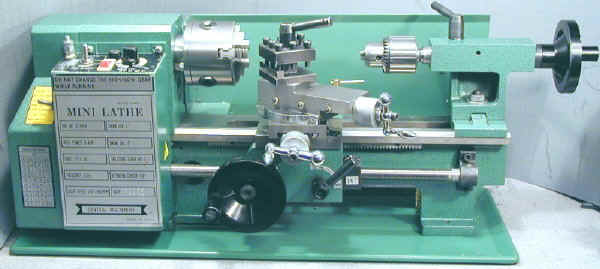
This page describes the construction and features of the 7×10 mini lathe. The specific model described is the Harbor Freight 7×10, but most of the information applies to similar lathes sold by other vendors including Enco, Micro-Mark, Northern Tool, Homier, Grizzly and others.
See the Versions page for lots more info on the various models available. There are differences in the power supplies and other features. Newer or older models may also differ in some respects from the specific model described here.
This little lathe has a lot of potential but has some shortcomings that you should be aware of before you decide to buy one, as you will learn in the following sections.
Fortunately, there is now a great deal of information available on this lathe on the web, so you are not on your own if you encounter a problem.
Introduction
Having owned an Emco Maximat lathe/mill in the seventies and having a little more spare time now that my kids are grown, I was in the market for a small lathe in Fall of 1999. After searching the web and looking at various options, I purchased the Harbor Freight 7×10 mini lathe. It is sold under the Central Machinery brand name and is Harbor Freight SKU# 33684.
This lathe is made in China, and has a lot of rough edges (literally and figuratively) out of the box. However, most of its flaws are fixable and if you spend some time improving it, you can end up with a very capable and reasonably precise little lathe.
This is a very sound approach if you need a lathe with more beef than the high-quality US-made Sherline or Taig micro-lathes, but can’t afford or justify spending $1500 or more for a high-quality minilathe such as the Prazi, Sakai or Emco. (Note 02/20/02 the Sakai company went out of business recently and these lathes are no longer manufactured).
If you need a precise and dependable tool right out of the box, this is probably not the right lathe for you. Update (09/12/02) This was true of my first 7×10, purchased in 1999. The quality of the 7x lathes seems to be steadily improving based on ones that I have bought since then and many reports on the 7x interest group.
I can now say that they are ready to go after cleaning off the packing grease and maybe making a few adjustments. It is still true, though, that you can sigificantly improve the performance by making various adjustments and modifications. End of update
Some owners have described it as more like buying a kit of parts which you then refine into a finished working tool. Many owners, myself included, find the process of improving the lathe to be as much fun as making the other stuff which we bought it for in the first place. If you need to get right to work, or just don’t want to spend your time fixing up a lathe, consider instead the excellent machines offered by Taig and Sherline.
The Harbor Freight 7×10 sells for $399 but sometimes goes on sale for $349 or even as low as $329. At that price, it is a lot of bang for the buck! It weighs about 80lbs – light enough for one person to move it easily, but heavy enough to turn some serious (by home shop standards) metal.
Harbor Freight also includes free shipping and even pays return shipping if you need to return something. Other companies charge $40-50 for shipping and a heavy item may cost you another $40 if you need to return it for some reason, so this is a valuable service.
Several vendors, such as Grizzly, Micro-Mark, Enco and others now sell variations of this lathe with different features, so choosing the best model for your needs is becoming a little more complicated that it was when I bought mine. To help you with this process see my mini-lathe versions page.
Terminology
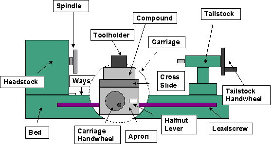
To gain a good understanding of the lathe, you will need to know the names of the various components, as illustrated below.
The carriage, in the circled area, consists of the apron, the vertical casting on which the carriage handwheel is mounted, and the saddle (not shown), the H-shaped casting that rides on the ways to which the apron is attached.
General Construction
In the photo below, the carriage and tailstock have been removed to show the basic construction of the lathe. This is the 7×10 model. The 7×12, despite it’s designation, is actually 4 inches longer. The bed is a single sturdy casting with cross braces.
Attached to the base of the bed is a sheet metal chip tray. A sheet metal chip/splash guard runs behind chuck and along the back of the lathe.
Varmint Al did not like these and removed them, but I find them pretty helpful in keeping chips under control. Well, come to think of it, the chips get all over the shop anyway, and the tray does have a way of getting small bolts, taps, drills, etc. hidden under its edge.
Four rubber feet are mounted on the bottom of the lathe under the chip tray. I removed these and bolted the lathe directly to my workbench after retapping the metric threads to 1/4-20.
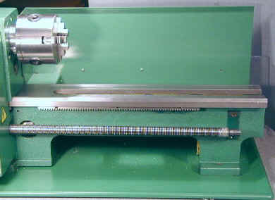
Here’s a view of the back of the lathe, showing the chip guard, motor cover and control levers.
Headstock and Control Levers
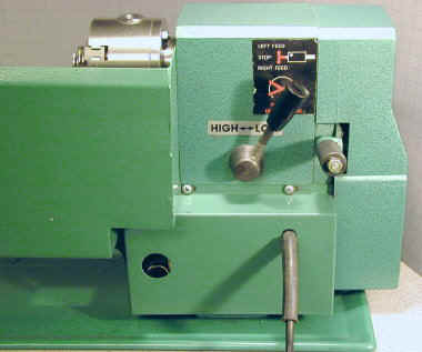
The headstock comprises the rectangular metal casting at the left end of the lathe. It contains the spindle shaft and its support bearings and the Hi/Lo speed shift lever and gears. Normally, the headstock is mostly hidden behind the electronics box and the spindle is hidden by the gear cover.
In the following photo these have been removed to reveal the headstock casting and spindle shaft. Instructions for removing and lubricating the headstock can be found on the Tuning page.
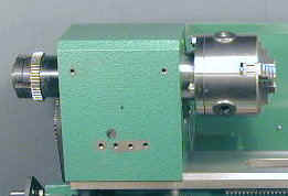
On the back of the headstock are two levers
- The tumbler gear lever
- The Hi/Lo speed lever
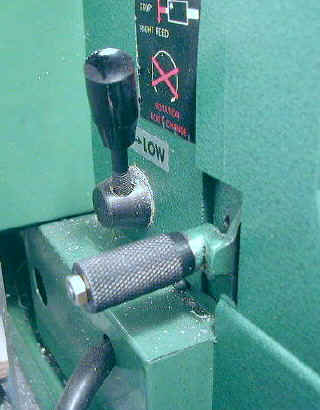
The tumbler gear lever sets the rotation of the leadscrew which advances the carriage under power. It has three positions:
- Forward (up) – carriage moves towards the headstock when spindle rotates forward
- Neutral (mid)
- Reverse (down) – carriage moves away from the headstock when spindle rotates forward
There is a knurled spring-loaded sleeve on the lever which must be pulled back with considerable force to move the lever from one position to another. A locking pin engages with detents in the headstock casting to hold the lever in place.
This is not a very robust design and has caused minor troubles for some users when the tumbler gears did not engage or disengage fully.
Tumbler gears are an unexpected feature on such a low cost lathe. They allow you to reverse the direction of the leadscrew relative to the direction of spindle rotation.
Note that this is not the same as merely reversing the spindle direction, which would also reverse the leadscrew rotation. The most common use of this feature is in cutting left-handed threads.
The Hi/Lo speed lever selects the spindle speed range by engaging different gear ratios within the headstock. In Lo range, the speed range is approximately 150 to 1500 RPM and in Hi range, 460 to 2900 RPM – at least that’s what’s marked on the speed control knob legend.
The Hi/Lo speed control lever should never be shifted when the lathe is moving and this fact is clearly marked on warning labels on the lathe.
Many 7×10 users recommend opening up the headstock and lubricating the gears and shift mechanism with white lithium grease. On mine, I was compelled to do this when the shift lever seized up after a few months of use.
A good workover with grease solved the problem and made the lathe run a little quieter. Opening up the headstock is probably best left until you are comfortable with other maintenance operations on the lathe.
Bed and Ways
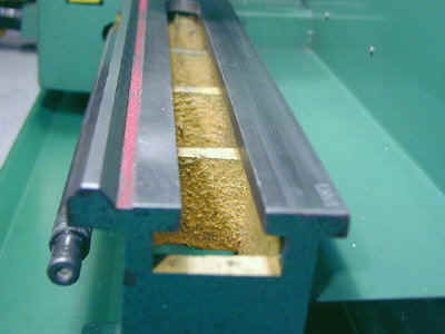
The bed is the main body of the lathe, made from rough but sturdy cast iron. The ways are the ground surfaces on the top side of the bed on which the carriage and tailstock ride.
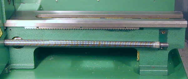
The ways have a inverted V-shaped ridge on the front side and are flat on the back side. A matching groove on the underside of the saddle rides along this ridge. The headstock casting also has a V-groove which aligns it with the ways. The ways are not hardened so you must be careful not to drop tools or the chuck on them or you will create dents and gouges.
Carriage and Saddle
The carriage supports the cross-slide, compound and tool post and moves along the ways under manual or power feed. It comprises the saddle, a casting that rides across the top of the ways, and the apron, a casting which extends down from the saddle in front of the lathe and supports the carriage handwheel, half nut assembly and threading dial.
The lever to the right of the carriage handwheel is the half-nut lever. It engages and disengages the power feed to the lead screw as described in a later section.
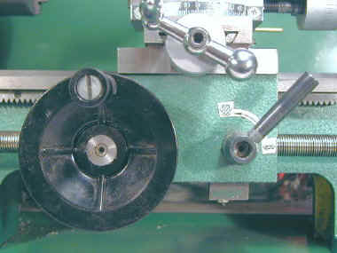
The carriage handwheel moves the carriage along the ways by means of a rack and pinion drive. The rack teeth are visible just below the ways in the photo above. The next picture shows the back side of the apron. The pinion is driven by a reduction gear connected to the handwheel.
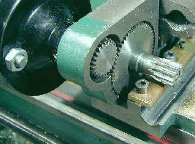
For short cuts, it is often more convenient to just use the carriage handwheel to advance the carriage, but it is hard to get a nice even finish like you get with power feed.
Cross Slide and Compound
The cross slide consists of a dovetailed slide that moves at a right angle to the ways. The compound is mounted on top of the cross slide. In the following picture the compound has been removed, showing the cross-slide mounted on the saddle. The compound bolts into the disk in the cross-slide which enables the compound to be rotated.
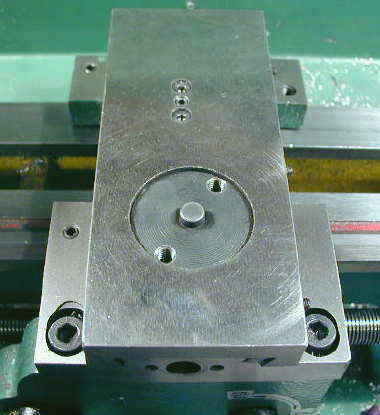
The cross feed advances the cutting tool into the work at a right angle to the workpiece by means of a leadscrew and handwheel. More expensive lathes have power feed capability on the cross feed but this lathe does not. It’s not a big limitation, though, given the small diameter of typical workpieces.
The compound sits on top of the cross slide and can be rotated to set the tool to advance at an angle to the workpiece. For example, by setting the compound at a 4 degree angle, you can cut shallow tapers suitable for making handwheels. An angle of 30 degrees is sometimes used so that advancing the compound handwheel by .001″ actually advances the tool by .0005″ (since sine of 30 = .500).
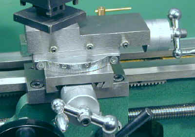
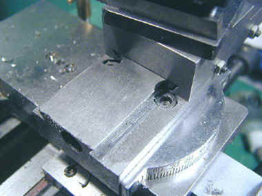
One particulary inconvenient feature of the lathe is the location of the locking screws for the compound. They are underneath the compound slide and to get to them you must crank the compound slide back almost to the end of its travel.
Partly because of this, I find that I don’t change the angle of the compound very often. (Note: around 11/03 I came up with a nice modification to solve this problem) Here’s a picture showing the compound cranked back to reveal the screws:
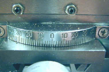
A coarse but still useful protractor scale is attached to the front of the compound as an aid to setting angles. Since the divisions are about 1 degree wide you won’t get a lot of precision but, most of the time, not much is needed. Older versions of the lathe and the SKU# 39916 version do not have this feature.
Three adjustable gib screws are visible along the side of the compound. Each consists of a set screw and lock nut. The set screws press against a steel gib strip on one side of the dovetail, enabling you to minimize any play between the sliding surfaces. A similar set of four screws (not visible in the picture) adjusts the cross slide.
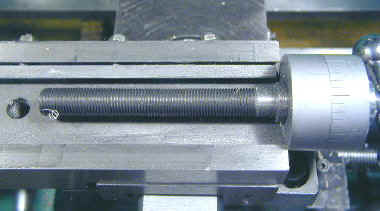
Here’s a picture of the underside of the cross slide showing the lead screw. The metal gib strip is visible just above the leadscrew.
Chromed handwheels with a ball on one end and a crank handle on the other are used to move the cross feed and compound. They work pretty well, allowing you to crank quickly or make small precise movements as needed.
Unfortunately, the screw head that holds them in place tends to scrape your knuckles when you are cranking. Also, on my lathe, at least, if the cross feed crank was at the low end of its swing, it could be hit by the handwheel handle of the carriage feed – thus shifting its setting and possibly driving the tool into the workpiece (not good).
For these reasons, I replaced the stock handles on my lathe with aluminum handwheels I made on the lathe.
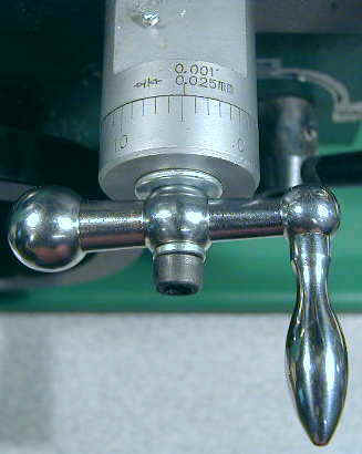
The cross feed and compound are marked with 40 divisions of .001″ which on newer models are a satin finish with nicely etched divisions and numbers. While accurate enough for most work, the divisions are not truly exactly .001″.
This is because the leadscrews for the cross feed and compound are actually 1mm thread pitch. Therefore, each rotation of the handwheel is actually .03937 inches instead of .04000 inches and a single division is thus .000984 inches rather than .00100 inches. Note: Micro Mark sells a 7×12 version of the lathe with true inch leadscrews and divisions.
Does this drive you crazy? Here again, you have to recognize the limitations of the machine and work around them. In practice, I find that much of the work I do requires precision of less than .005 anyway.
When I need more accuracy I use a dial indicator and/or frequently check the diameter of the workpiece (with the lathe stopped!) using a dial caliper. Or, if you are handy with a calculator, you can just calculate the number of divisions you need to move the handwheel to get the true distance you want.
Toolpost and Tools
The toolpost can hold up to four tools at once, each locked in place by hex-head cap screws. The newer model lathes (1999 and later) use 5/16″ tools, but some older models and the Homier 7×12 use 3/8″ tools.
Strictly speaking, these lathes were presumably designed to use metric tool blanks, so imperial size tools will probably not align exactly with the centerline. You can use shims or an adjustable tool holder to solve this problem.
Tools can be ready-made carbide tipped tools of various types or high speed steel (HSS) ground to shape by the user from commonly available tool blanks. 5/16″ tool blanks can be obtained from most machine tool suppliers such as Enco, J&L, Grizzly, etc., for around $1.00 each.
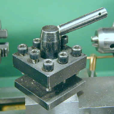
The toolpost rotates around a large bolt on top of the compound slide and is locked in place by a clamping lever. You can set it to any convenient angle. Underneath the toolpost is a spring-loaded indexing pin which engages with detents in the base of the tool holder. I, and some others, did not find this useful and removed the indexing pin.
No cutting tools are provided with the lathe and you can’t do much without them, so be sure to order about 5-10 blanks or premade tools when you order your lathe! Of course, if you intend to grind your own HSS tools, you will need a bench grinder. Suitable 6″ grinders are available for under $50 from many sources. I bought an Ohio Forge brand from Home Depot and have been pretty happy with it. Here’s a link to my tool grinding info.
Harbor Freight sells a ‘quick change tool set’ for about $79 which seems to be intended for use with the 7×10 lathe. You do not need it, since the lathe does come with a tool holder.
Reviews on the quick change holder have been mixed: some users have returned them and those who have kept them have found it to be of limited value but useful for boring and knurling.
More recently, HF started selling a QC toolpost for $99. This one seems to be OK, but I don’t have much feedback on it yet. JW Early has modified several 7×10’s to use a commercially available QC toolpost. If you’re interested, check out JW Early’s QC toolpost mod.
You can make your own toolholders for holding boring tools, knurling tools and other special purpose tools. I will add info on this later.
Leadscrew, Power Feed
Extending from the gear drive train on the left side of the headstock, through the speed control box and out to a pillow block supporting the right end, the leadscrew can be driven under power to advance the carriage in either direction for turning or threading.
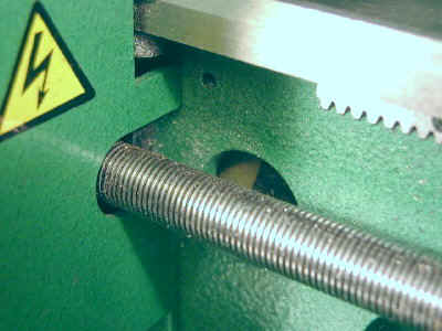
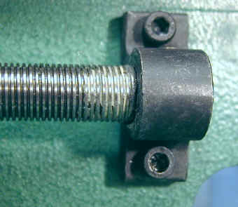
The rotational speed of the leadscrew relative to the spindle speed can be adjusted by manually adding and removing gears to and from the gear train. These adjustable gearing ratios also, of course, determine the number of threads per inch during threading operations.
Half-Nut and Threading Dial
A standard feature on all lathes that have power feed, the half-nut consists of two parts threaded to mate with the leadscrew which are engaged from above and below the leadscrew by turning the half-nut lever. The lever engages or disengages the carriage from the turning leadscrew to advance or stop motion of the carriage along the ways.
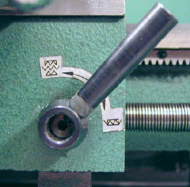
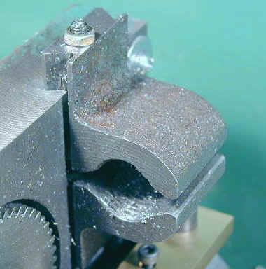
On the 7×10 the half-nut pieces are cast iron and ride in a crude dovetail to engage the leadscrew. Adjusting screws, accessible from the right side of the apron, can tighten or loosen the grip of the half-nut on the leadscrew. When the half nut lever is in the up position it is disengaged; in the down position, engaged.
If the leadscrew is turning when the half nut is engaged the carriage will move towards the headstock or tailstock depending on the direction of leadscrew rotation as determined by the leadscrew direction lever on the back of the headstock.
Most often the carriage is advanced towards the headstock when making “long” (a relative term on this lathe) turning cuts. Of course you must pay attention when cutting under power and disengage the half nut as the cutting tool approaches the chuck.
You can reduce this risk in some cases by reversing the leadscrew direction so that you are cutting away from the chuck. This is especially handy for short threading cuts where the carriage is moving fast compared to the chuck speed.
Cutting Screw Threads
With the supplied gears, the lathe can cut a variety of threads – many more, in fact, than are listed on the chart on the gear cover. Metric threads can also be cut within reasonable accuracy, using the appropiate combinations of gears. Check out Varmint Al’s site for good info on these ratios and gear cutting. For a detailed tutorial on thread cutting, you may wish to subscribe to the Premium Content Threading page.
Quite some time ago, Varmint Al created a BASIC program to calculate the required gears needed to cut a specified thread pitch. Paul Bussières has created a much more sophisticated version that you really have to see to fully appreciate. Click here to download a zip file containing the program and support files. It is pretty small and downloads quickly.
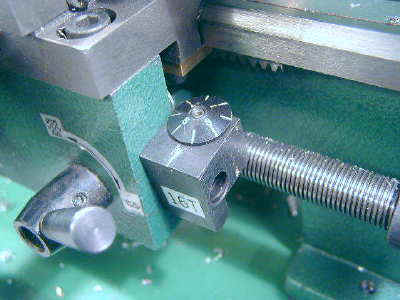
The threading dial is used to engage the half-nut lever at exactly the right time when cutting threads. A chart on the front of the gear cover shows the thread dial engagement settings for various thread pitches. If the leadscrew is rotatating but the half-nut is not engaged, the thread dial turns slowly. Once the half-nut is engaged, the thread dial does not turn.
Gary Giddings posted an excellent explanation of how the threading dial works:
The main function of the threading dial is to act as an “advisor” on when to close the half-nuts onto the leadscrew. On the Homier 7×12, the threading dial (called the “indicator” there) has 8 divisions, with the odd divisions marked 1, 3, 5, and 7.
So, the unmarked divisions can be thought of as 2, 4, 6, and 8. The gear on the threading dial shaft (that mates with the leadscrew) is a 16-tooth gear. Thus (with the half-nuts open and moving the carriage back and forth), the threading dial revolves once for each 16 leadscrew-threads that pass by. Or, one revolution for each inch of carriage travel.
One can try to close the half-nuts at any time. At some locations the thread ridges on the half-nut will be aligned with the grooves on the leadscrew and the nut will close smoothly, as it should. However, at other times, the nut will not be aligned properly with the leadscrew, and the nut ridges will ride on the top of the leadscrew ridges, and the nut will not close properly.
With the lathe off, but just moving the carriage, one can easily try this (gently) and feel the difference. So, there are 16 places in each inch of carriage travel where the nuts will close properly … sixteen can-close (properly) positions. The threading dial divisions line up with the index mark for every other one of these 16 can-close positions, showing us visually that we are properly located to close the half-nut and properly mesh with the leadscrew.
Call these can-close positions the “marked” positions. So, if one (again gently) tries to close the half-nuts just before a division passes the index mark, one should be able to feel the nuts drop into place just as the division reaches the index mark – at one of the “marked” positions on the leadscrew.
In a similar manner, one can find and feel the eight can-close positions that lie exactly half-way between each of the marked threading dial divisions. Call these the “un-marked” positions. Try to gently close the half-nuts about one third of the way between divisions, and the closure into the “un-marked” leadscrew position should happen exactly between the index marks. So, the threading dial is, at least, acting as a visible “can-close” indicator for the half-nuts.
Using the half-nut during threading: Think of (or sketch to scale) the threaded rod that one wants to make and the leadscrew placed side by side. Start with a 16 track per inch (tpi) rod. Notice (in your mind) that every groove on the rod lines up with a groove on the leadscrew.
In cutting this thread, one could close the half-nut in any groove of the leadscrew and the tool would still follow the same path down the rod while cutting the thread Next, think of a 32 tpi rod … where two grooves of the rod are spanned by one groove of the leadscrew.
Again, any closing position of the half-nut will work. This is true for any multiple of the leadscrew pitch (like 16, 32, 48, or 64). Now, think of an 8 tpi rod next to the leadscrew and notice that the rod grooves only line up with every other groove on the leadscrew (call these the “marked” grooves on the leadscrew).
Now, making repeated cuts on this rod is easily done if the half-nuts are consistently closed at any of the “marked” positions, avoiding the “un-marked” closure positions. This is true for any multiple of 8 tpi (8, 16, 24, etc.) Next, take 12 tpi (an odd multiple of 4).
Here, the threads line up at the start and at each half-inch along the leadscrew (each 6 threads on the rod, and 8 threads on the leadscrew). So, the opposite indicator marks, like 1 and 5 (or 3 and 7) would work. Next to last, take a 9 tpi rod next to the leadscrew (an odd whole number of threads per inch).
Here, the threads line up only at the start of each inch along the leadscrew (9 threads on the rod, and 16 threads on the leadscrew). So, any one indicator mark, like 1 only (or 3 only, etc.) would work.
Finally, take a 25.4 tpi thread next to the leadscrew. The only place the threads match is at the start point. At one inch, at two inches, etc. – no match (they do match at 5 inches, but that does not do us any good here) So, best to keep the half-nuts always closed in these cases, and reverse back to the start point for the next pass.
Reading the chart “Indicator Table” on the Homier: The numbers punctuated with periods (like 1.3.5.7 or 1.5) should be read as if they are written with commas and spaces (as 1, 3, 5, 7 or 1, 5) and they mean use any of the mentioned settings. The designation “1~8” means 1 through 8 – use any of the settings (1, 2, 3, 4, 5, 6, 7, or 8).
There are only 4 designations in the chart: Any (1~8): for any multiple of 8 tpi (8, 16, 24, 32, 40, 48 tpi) Odd Number (1.3.5.7): for any odd multiple of 4 (12, 20, 28, 36, 44, 52 tpi) One or Five (1.5): for an even tpi not covered above (14, 18, 22, 26, 38) One Only (1): for all odd tpi (13, 19, and others) The simple answer – always use “1”.
(Note that this really means always use the SAME number to re-start each new cut pass). Sketching the leadscrew and rod threads has helped me to understand the threading dial. I hope this helps somebody else.
Change Gears and Tumbler Gears
On the left side of the lathe is a plastic cover which conceals the gear train that drives the leadscrew. This cover is held in place by two 4mm bolts. Removing the cover gives access to the gear train.
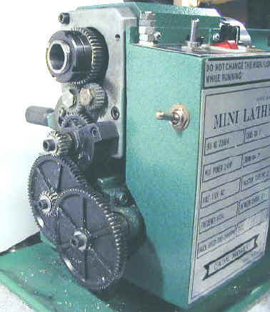
The small white nylon gears are the tumbler gears which are controlled by the leadscrew direction lever to determine the rotational direction of the leadscrew. In the neutral position neither gear should be touching the metal gear on the spindle shaft.
Additional gears (not shown) are provided and together allow the lathe to cut a wide variety of inch and metric threads. Expensive lathes have gear sets attached to quick change levers to quickly and conveniently select the desired thread.
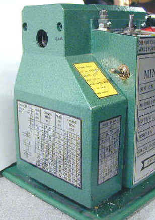
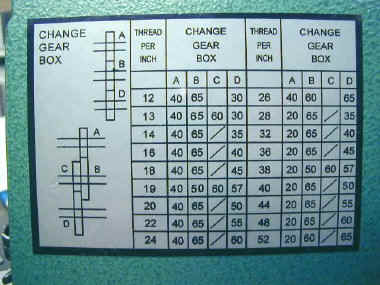
On this lathe you must manually remove and add the proper gears each time you need a different thread pitch. This is a pain, but for most users, threadcutting is done infrequently, so the invconvenience is tolerable. For normal power feed operation, the gear train is set to 256TPI. Some of the possible thread pitches and gear combinations are shown on a chart on the left end of the lathe:
Tailstock, Centers and Drill Chuck
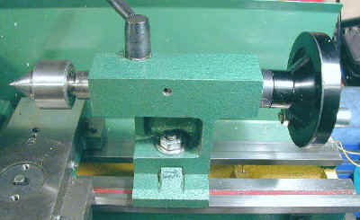
The tailstock casting rides on the ways and is locked in place by means of a nut and 17mm wrench. A handwheel advances the tailstock spindle for drilling and tapping operations. The spindle bore is a #2 Morse Taper and a #2MT ball-bearing live center and a dead center are supplied with the lathe.
A tailstock chuck is not supplied and is an essential accessory for drilling, so be sure you order one when you order your lathe. A 1/2″ chuck is a good choice to start with but you may find that you want a 3/8″ or 1/4″ chuck later on.
The chuck is mounted in the tailstock spindle using a #2MT arbor, so you will also need to purchase the arbor. The back of the chuck will either be threaded or will have its own taper – usually a Jacobs taper – so you must get an arbor that also matches the chuck. I got my 1/2″ chuck from Grizzly (P/N G1649, $16.95) along with an arbor (P/N G1434, $7.95) that is #6 JT to #2 MT.
#2 MT arbors often have a flat tang on the end and are too long to fit in the shaft of the tailstock spindle. Therefore the tang must be removed. This can be done by cutting with a ‘chop saw’, a diamond or carbide tool in a Dremel or similar tool. I used a fiber cutoff blade in my 10″ radial arm saw and clamped the arbor between two pieces of wood in my drill press vise. Check the back postings on the 7×10 interest group for much discussion on this topic.